Sequence of operations, Technical guide mua ii controller 14, Mua operation overview – Orion System MUA II Controller User Manual
Page 14: Mua modes
Technical Guide
MUA II Controller
14
Sequence Of Operations
MUA Operation Overview
The MUA controller is designed to control an HVAC unit to provide
fresh air of neutral temperature (and humidity if required) into a building
that has a net air loss caused by air being exhausted from the building.
The MUA controlled HVAC unit can have heating, cooling and/or dehu-
midification capabilities. Heating and cooling sequences are controlled
based on outside air temperature. Whenever the outside air temperature
is outside of the heating or cooling setpoints, the appropriate heating or
cooling staging will be initiated to bring the supply air temperature
within the required range and maintain it at that condition.
The outside air humidity and temperature in the form of a dewpoint
temperature setpoint control the MUA controller dehumidification se-
quence. Since dewpoint temperature by definition is the temperature at
which water vapor condenses from the air mixture, it is good indicator of
when dehumidification is required. The controller uses the outside air
humidity sensor in conjunction with an outside air temperature sensor
to calculate the dewpoint temperature of the outside air. If the outside
air dewpoint exceeds the dewpoint setpoint with respect to the outside
air temperature, the dehumidification sequence will be initiated to bring
the supply air dewpoint temperature within the required range and
maintain it at that condition.
MUA Modes
This controller has a total of 6 modes of operation that behave differ-
ently. These are divided into 1 unoccupied mode and 5 occupied modes.
The operation of each of these modes is explained on the following
pages.
Unoccupied
In this mode the controller will shut off the cooling, the heating and the
blower.
Occupied
In the occupied cycle the unit has the following modes:
•
Cooling
•
Vent
•
Dehumidification
•
Heating
•
Temperature Protect Mode
The diagrams that follow depict the operational modes of the MUA II
controller.
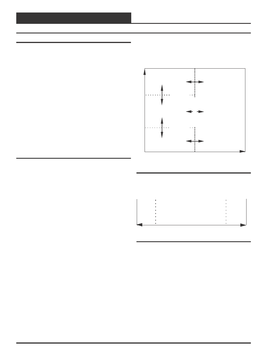
Figure 17 illustrates how the OAT (Outdoor Air Temperature) and the
Dewpoint Temperature initiate the various normal operational modes.
Figure 18 illustrates the Temperature Protect Modes which are deter-
mined by the Supply Air Temperature.
Dewpoint Temperature
Cool Setpoint
Cool Setpoint
=
Supply Setpoint + Cool Deadband
Heat Setpoint
=
Supply Setpoint - Heat Deadband
Dehumidification
Heat Setpoint
Vent
Heat
Cool
Out
door
Air
T
emperature
(OA
T
)
Dewpoint
S
etpoint
Figure 17: Operational Modes
Low SAT
Cutoff Limit
0 F
°
150 F
°
High SAT
Cutoff Limit
(SAT) Supply Air Temperature
Figure 18: Temperature Protect Mode
Cool
This mode occurs when the controller reads an OAT one Cooling
Deadband above the Supply Air Setpoint and a Dewpoint Tempera-
ture below the Dewpoint Setpoint. The migration table for this mode
is shown below.