Vav/cav controller technical guide 19 – Orion System MUA II Controller User Manual
Page 19
VAV/CAV Controller
Technical Guide
19
If the COMM LED does not operate as indicated above, first check the
address switch setting. Verify the address switch as outlined in LED
(Diagnostic LED) Operations below. If the address switch setting is
correct and the COMM LED still does not behave as indicated above,
check to be sure the operators interface is connected correctly. The
System Manager must be connected to a local communications loop
either at the MUA II controller as shown in Figure 20 or to another
controller on the same local communications loop. If you are using the
Modular Service Tool, verify that it is plugged in securely to the DIN
connection on the MUA II controller. See Figure 20 for DIN connec-
tor location.
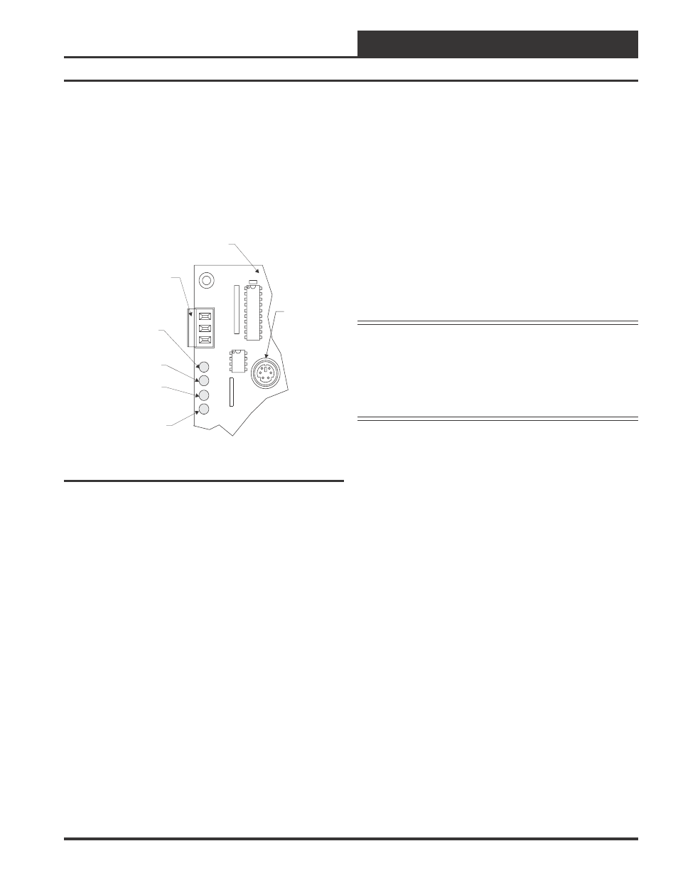
COMM
PWR
LED1
LED2
R
SHLD
T
COMM
(COMM) Communications
MUA II Controller Board
Communications Terminals
System Manager Can Be
Connected Here
(PWR) Power
(LED2) Diagnostic
(LED1) Not Used
DIN Connector
For Modular
Service Tool
Figure 20: LED & Interface Connection Locations
If the COMM LED still does not behave correctly, check the voltages at
the communications terminal block. Be sure the board is powered up for
this test. Unplug the communications terminal block from the board and
check the DC voltage between T and SHLD and between R and SHLD.
Check the voltage with a digital multimeter set to DC volts. The voltage
should be between 2.4 to 2.5 VDC between SHLD and either T or R. If
your voltage is not in this range, you probably have a damaged driver
chip that must be replaced. For driver chip replacement instructions,
please see the Orion Controls System Installation & Troubleshooting
Guide for more information or contact the factory for further assistance.
LED2 (Diagnostic LED) Operations
When power is first applied, LED2 is turned off for 5 seconds. At this
time LED2 will “blink” to indicate the setting of the address switch and
then extinguish for another 5 seconds. Verify that the address switch
setting is correct by counting the number of blinks. If the address switch
setting is not correct, remove the communication loop terminal plug
from the controller and then the power terminal plug. Correctly set the
address switch setting (See Figure 15) with the dip switches on the
controller, reconnect the power connection and then the communication
loop. Reapply power to the controller and observe the blink code to
verify the address is set correctly.
Note:
Power to the Controller being addressed must always
be cycled after changing address switch settings in or-
der for the changes to take effect. Always unplug the
communications terminal block before removing the
power terminal block from the board. When finished
reinstall the power terminal block first and then the
communications terminal block.
If LED2 blinks the correct address, your board is addressed correctly. If
it does not light up at all, the board is not operating correctly and could
be defective.
If all of these tests are made and the controller still doesn’t operate, see
the Orion Controls System Installation & Troubleshooting Guide for
more information or contact the WattMaster Technical Support Toll Free
Number at 866-918-1100 for further assistance.