Two condenser head pressure module, Sequence of operation, Technical guide – Orion System Two Condenser Head Pressure Module User Manual
Page 13
Technical Guide
Two Condenser Head Pressure Module
13
Sequence of Operation
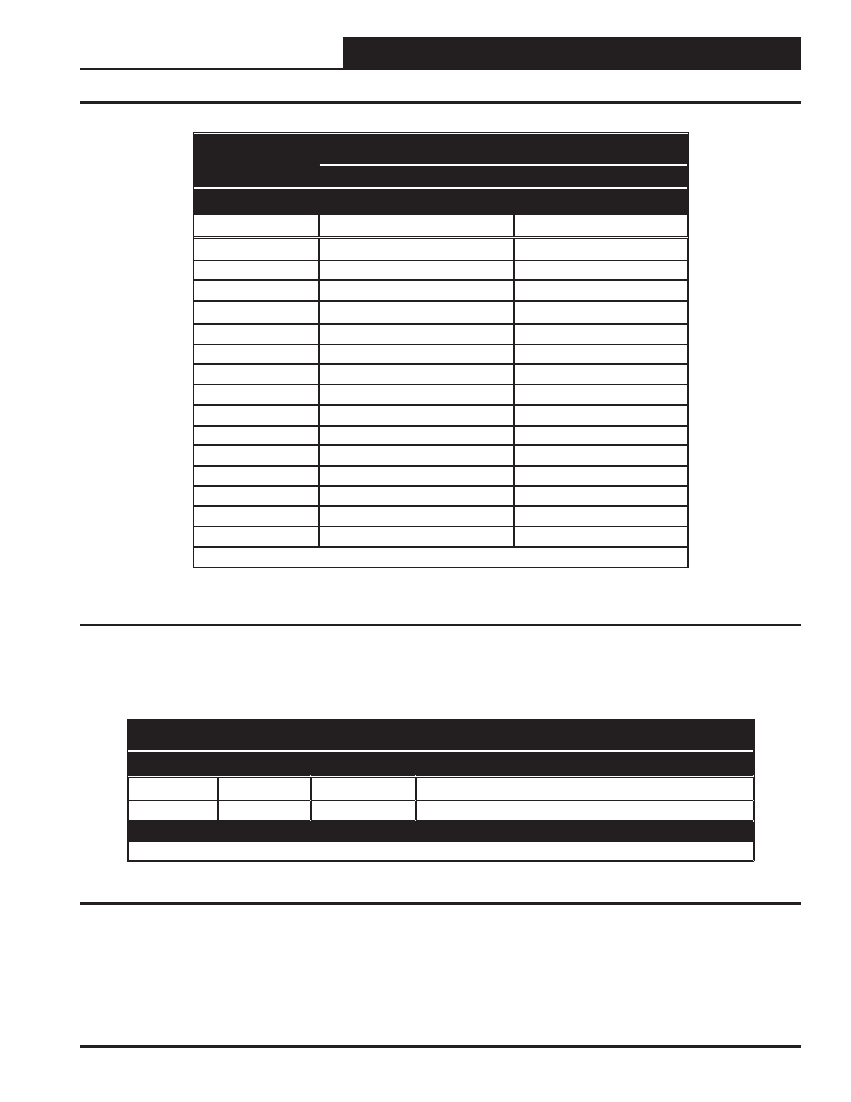
Table 2: OPTIONS Dip Switch/Head Pressure Setpoint Settings for Stand-Alone Operation
OPTIONS Dip
Switch Settings
Head Pressure Setpoint
Air Cooled Condenser
Water Cooled Condenser
Binary Value
R410-A
R410-A
0
340 (DEFAULT)
235 (DEFAULT)
1
260
210
2
270
220
3
280
230
4
290
240
5
300
250
6
310
260
7
320
270
8
330
280
9
340
290
10
350
300
11
360
310
12
370
320
13
380
330
14
390
340
15
400
350
NOTE: You must cycle power after setting Dip Switch values.
ADDRESS Dip Switch Settings
Switch 1
Switch 2
Default SP
Description of Default Head Pressure Setpoint
0
0
340
Air Cooled Condenser using R410-A Refrigerant
1
0
235
Water Cooled Condenser using R410-A Refrigerant
Switch 1 determines Air or Water Cooled Condenser
NOTE: You must cycle power after setting Dip Switch values.
Table 3: ADDRESS Dip Switch Condenser Type Settings for Stand-Alone Operation