Two condenser head pressure module, Appendix for version 1.04 and earlier, Technical guide 20 – Orion System Two Condenser Head Pressure Module User Manual
Page 20: Version 1.04 and earlier, Vcm-x / sa connection, Condenser fan a ecm motor, Condenser fan b ecm motor, Condenser signal b, Condenser signal a
Two Condenser Head Pressure Module
Technical Guide
20
Appendix for Version 1.04 and Earlier
Version 1.04 and Earlier
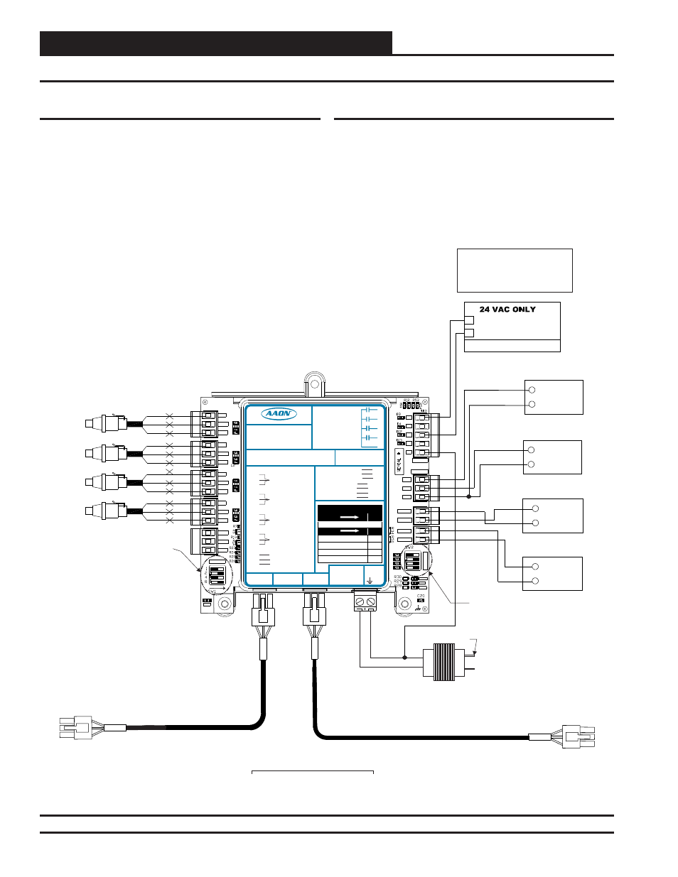
Version 1.04 and earlier have several differences from version 1.07 and
later. Please refer to the Dipswitches in Figures 9 & 10 and the Tables
10 & 11 for detailed information.
Figure 9: Version 1.04 and Earlier One Condenser Head Pressure Module Wiring Diagram
(VCM-X / SA Connection)
SIG
GND
+V
BK
RD
WH
SIG
GND
+V
BK
RD
WH
SIG
GND
+V
BK
RD
WH
SIG
GND
+V
BK
RD
WH
COM
Condenser Fan A
ECM Motor
+
Head Pressure Transducers
0 - 667 PSI
(One Per Refrigerant Circuit)
OE370-23-HP2C-C
Two Condenser Head Pressure Module
OPTIONS Dip Switch Setting Not
Required When Connected To
VCM-X E-BUS Controller
or SA E-BUS Controller
+5V
SIG 2
GND
OP
T
IO
N
S
ALARM
ANALOG
STAT
+5V
COMM
GND
SIG 4
GND
BIN 2
R1
R2
GND
RELAYS
ADDRESS
SIG 3
+5V
GND
BIN 1
COM
+5V
SIG 1
R3
R4
Rc
AO1
AO2
PWM1-
PWM1+
PWM2-
PWM2+
PWR
COM
Condenser Fan B
ECM Motor
+
COM
+
Condenser
Signal B
COM
+
Condenser
Signal A
Connect To Other
WattMaster-Approved
E-BUS Expansion Module(s)
HSSC Cable
24 VAC Transformer
3 VA Minimum
Line Voltage
24 V
A
C
GND
WARNING!! Ob
P l it ! All
CONDENSER A ENABLE
R1
HVAC UNIT CONNECTION
R3
CONDENSER B ENABLE
NOTE:
NORMALLY OPEN AND
RATED FOR 24 VAC POWER
ONLY - 1 AMP MAXIMUM LOAD
ALL RELAY OUTPUTS
ARE
COMM
HSSC Cable
Connect To VCM-X E-BUS
Controller
Set ADDRESS Dip Switch
1 to ON for Water Cooled
or to OFF for Air Cooled.
Currently showing OFF for
Air Cooled.
If Using (2) Modules, Set
ADDRESS Dip Switch 2 to
OFF for Address 1 or to ON
for Address 2.
ADDRESS Dip Switch 4
should always be set to ON
to make reversing valve
"ON to Cool / OFF to
Heat". Currently showing
ON.
LED BLINK CODES
LED NAME
STAT
BLINKS QTY. OF SENSORS INSTALLED
LED NAME
ALARM
NO PROBLEMS
0
NO SENSORS DETECTED
1
HIGH HEAD PRESSURE DETECTED
2
LOW HEAD PRESSURE DETECTED
3
WattMaster Label
Rev.: 1H
#LB102081
E-BUS
Connector
E-BUS
Connector
+5V
SIG 1
GND
+5V
SIG 2
GND
+5V
SIG 3
GND
+5V
SIG 4
GND
+24
VAC
GND
BIN 1
BIN 2
COM
HEAD
PRESSURE
TRANSDUCER #1
HEAD
PRESSURE
TRANSDUCER #2
HEAD
PRESSURE
TRANSDUCER #3
HEAD
PRESSURE
TRANSDUCER #4
COMMON
PWM2+
Two Condenser Head Pressure Module
2C
Orion No.:OE370-23-HP
AAON Coil No.:
30310
Circuit A1
Circuit A2
Circuit B1
Circuit B2
www.aaon.com
AO1
AO2
GND
COND. A & B ENABLE
COOL ENABLE
RELA
Y
C
ONT
A
CT
RA
TING
IS
1
A
MP
MAX
@
24
V
A
C
COND. A ENABLE
COND. B ENABLE
COND. A SIGNAL
COND. B SIGNAL
COOL ENABLE
COOL ENABLE
PWM1-
PWM1+
PWM2-
COND. FAN A
COND. FAN B
COND. FAN A
COND. FAN B
GND
R1
R2
R3
R4
RC
RELAY COMMON
VCM-X / SA Connection
Version 1.04 and earlier do not utilize Dipswitch 2 when the module is
connected to a VCM-X or SA Series Controller.