Two condenser head pressure module, Technical guide 8, Condenser fan a ecm motor – Orion System Two Condenser Head Pressure Module User Manual
Page 8: Condenser fan b ecm motor, Condenser signal b, Condenser signal a
Two Condenser Head Pressure Module
Technical Guide
8
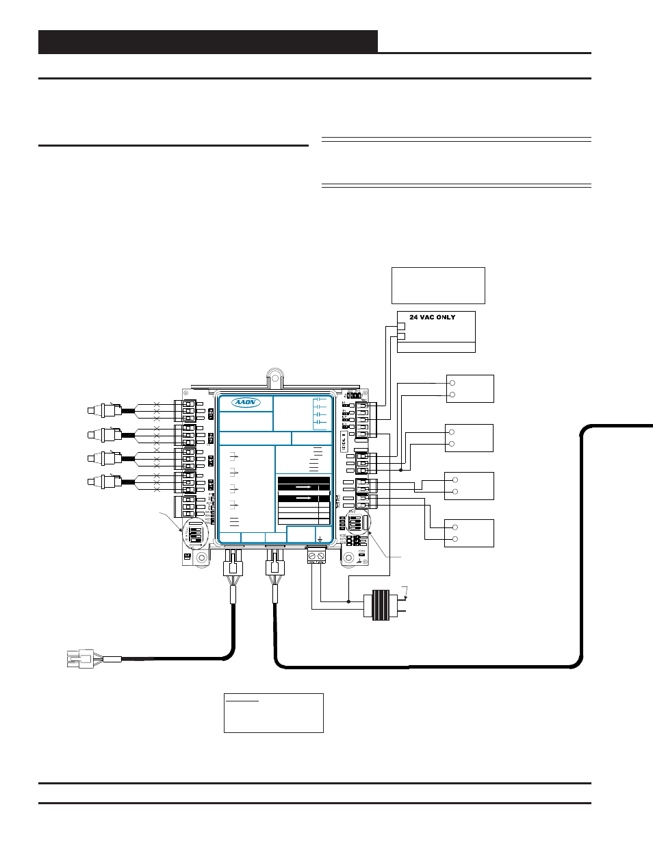
E-BUS Controller to Two Condenser Head Pressure Module Wiring
VCM-X Modular E-BUS or VCM-X WSHP
E-BUS Controller to Two Condenser
Head Pressure Module Wiring
Up to (2) Two Condenser Head Pressure Modules can be daisy-chained
together and connected to the E-BUS Controller using a modular HSSC
cable. The Two Condenser Head Pressure Module requires a 24 VAC
power connection with an appropriate VA rating. See Figure 5 below
for wiring.
Any E-BUS Module can be connected to the E-BUS Controller’s E-BUS
port or can be daisy-chained together using HSSC cables.
NOTE: Contact Factory for the correct HSSC cable length for
your application. Cables are available in ¼, ½, 1, 2, 3,
4, and 5 Meter lengths and 100 and 150 Foot lengths.
Figure 5: VCM-X E-BUS Controller to Two Condenser Head Pressure Module Wiring Diagram
SIG
GND
+V
BK
RD
WH
SIG
GND
+V
BK
RD
WH
SIG
GND
+V
BK
RD
WH
SIG
GND
+V
BK
RD
WH
COM
Condenser Fan A
ECM Motor
+
Head Pressure Transducers
0 - 667 PSI
(One Per Refrigerant Circuit)
OE370-23-HP2C-C
Two Condenser Head Pressure Module
OPTIONS Dip Switch Setting Not
Required When Connected To
VCM-X E-BUS Controller
or SA E-BUS Controller
+5V
SIG 2
GND
OP
T
IO
N
S
ALARM
ANALOG
STAT
+5V
COMM
GND
SIG 4
GND
BIN 2
R1
R2
GND
RELAYS
ADDRESS
SIG 3
+5V
GND
BIN 1
COM
+5V
SIG 1
R3
R4
Rc
AO1
AO2
PWM1-
PWM1+
PWM2-
PWM2+
PWR
COM
Condenser Fan B
ECM Motor
+
COM
+
Condenser
Signal B
COM
+
Condenser
Signal A
Connect To Other
WattMaster-Approved
E-BUS Expansion Module(s)
HSSC Cable
24 VAC Transformer
3 VA Minimum
Line Voltage
24 V
A
C
GND
WARNING!! Observe Polarity! All
boards must be wired with GND-to-
GND and 24 VAC-to-24 VAC.
Failure to observe polarity could
result in damage to the boards.
CONDENSER A ENABLE
R1
HVAC UNIT CONNECTION
R3
CONDENSER B ENABLE
NOTE:
NORMALLY OPEN AND
RATED FOR 24 VAC POWER
ONLY - 1 AMP MAXIMUM LOAD
ALL RELAY OUTPUTS
ARE
COMM
HSSC Cable
Connect To VCM-X E-BUS Controller
Set ADDRESS Dip Switch 1 to ON for
Water Cooled or to OFF for Air Cooled.
Currently showing OFF for Air Cooled.
If Using (2) Modules, Set ADDRESS Dip
Switch 2 to OFF for Address 1 or to ON
for Address 2.
ADDRESS Dip Switch 4 should always
be set to ON to make reversing valve
"ON to Cool / OFF to Heat". Currently
showing ON.
Set to OFF if Using (1)
Module. Currently showing OFF.
Set ADDRESS Dip Switch 3 to ON to
disable Circuit B alarms when only one
Condenser is Used. Currently showing
OFF.
LED BLINK CODES
LED NAME
STAT
BLINKS QTY. OF SENSORS INSTALLED
LED NAME
ALARM
NO PROBLEMS
0
NO SENSORS DETECTED
1
HIGH HEAD PRESSURE DETECTED
2
LOW HEAD PRESSURE DETECTED
3
WattMaster Label
Rev.: 1H
#LB102081
E-BUS
Connector
E-BUS
Connector
+5V
SIG 1
GND
+5V
SIG 2
GND
+5V
SIG 3
GND
+5V
SIG 4
GND
+24
VAC
GND
BIN 1
BIN 2
COM
HEAD
PRESSURE
TRANSDUCER #1
HEAD
PRESSURE
TRANSDUCER #2
HEAD
PRESSURE
TRANSDUCER #3
HEAD
PRESSURE
TRANSDUCER #4
COMMON
PWM2+
Two Condenser Head Pressure Module
2C
Orion No.:OE370-23-HP
AAON Coil No.:
30310
Circuit A1
Circuit A2
Circuit B1
Circuit B2
www.aaon.com
AO1
AO2
GND
COND. A & B ENABLE
COOL ENABLE
RELA
Y
C
ONT
A
CT
RA
TING
IS
1
A
MP
MAX
@
24
V
A
C
COND. A ENABLE
COND. B ENABLE
COND. A SIGNAL
COND. B SIGNAL
COOL ENABLE
COOL ENABLE
PWM1-
PWM1+
PWM2-
COND. FAN A
COND. FAN B
COND. FAN A
COND. FAN B
GND
R1
R2
R3
R4
RC
RELAY COMMON