Two condenser head pressure module, Module overview, Technical guide – Orion System Two Condenser Head Pressure Module User Manual
Page 3: 3overview, Features, Figure 1: two condenser head pressure module, Distribution module to e-bus interface, Capable of monitoring a reverse valve signal
Technical Guide
Two Condenser Head Pressure Module
3
Overview
NOTE: Software version 1.04 and earlier contain a few
differences from version 1.05 and later. For version
1.04 and earlier details, please see the Appendix.
The version number can be found on the upper right
of your module.
The Two Condenser Head Pressure Module (OE370-23-HP2C) monitors
four individual head pressure transducers and controls two Condenser
Fans or Water Valves on units with two physically separate condenser
sections. The highest reading of head pressure transducers 1 & 2 controls
Condenser Signal A. The highest reading of head pressure transducers 3
& 4 controls Condenser Signal B. If this is a heat pump unit, the module
is able to detect when the unit is in Heat Pump Heating mode and will
force the condenser signal to 100% until it leaves this mode.
The Two Condenser Head Pressure Module is designed to work stand-
alone by using its OPTIONS dip switch to adjust the Head Pressure
setpoint.
Up to (2) Two Condenser Head Pressure Modules can also be daisy-
chained together and connected to the VCM-X Modular or VCM-X
WSHP Controller using the E-BUS Distribution Module, allowing the
Module(s) to receive setpoints from the Controllers, or the Module(s)
can be daisy-chained together and directly connected to the VCM-X
Modular E-BUS or VCM-X WSHP E-BUS Controller. See chart on
page 2 for part numbers.
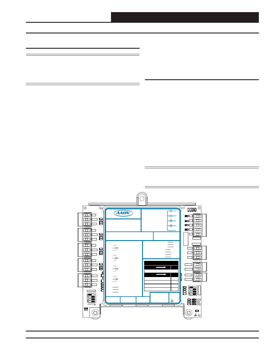
Module Overview
Figure 1: Two Condenser Head Pressure Module
The Two Condenser Head Pressure Module also provides a pulse
width modulation (PWM) signal or voltage output signal to control the
condenser fans.
The Two Condenser Head Pressure Module requires a 24 VAC power
connection with an appropriate VA rating.
Features
The Two Condenser Head Pressure Module provides the following:
Can be operated stand alone or up to (2) modules can be
daisy-chained together and connected to a VCM-X
Modular or VCM-X WSHP Controller using the
E-BUS
Distribution Module to E-BUS interface
Up to (2) modules can be daisy-chained together and
directly connected to a VCM-X Modular E-BUS
or VCM-X WSHP E-BUS Controller
Monitors up to four individual head pressure transducers
Provides control of Condenser Output Signals based on the
highest reading of head pressure transducers
Capable of monitoring a Reverse Valve Signal
Forces Condenser Fans to 100% while in the Heat Pump
Heating
Mode
NOTE: The Two Condenser Head Pressure Module contains
no user-serviceable parts. Contact qualifi ed technical
personnel if your Module is not operating correctly.
1003
1002
10uF
300
1
2
4
8
SERIA
L
#
C2
D3
D4
R7
R9
R11
R12
R13
R14
R23
R24
R25
R26
R28
R29
R30
SW1
D12
D13
R53
R54
TB3
C20
R34
R
50
SW2
+5V
SIG 2
GND
1003
1002
10uF
1003
1002
10uF
1003
1002
10uF
4751
4751
4751
4751
OF
F
OF
F
OP
T
ION
S
ALARM
STAT
COMM
300
4
4
1002
1002
1002
1002
1002
1002
1002
1002
RELAYS
ANALOG
ADDRESS
+5V
SIG 3
GND
+5V
SIG 4
GND
BIN 1
COM
+5V
SIG 1
GND
BIN 2
R1
R2
R3
R4
Rc
AO1
AO2
GND
PWM1-
PWM1+
PWM2-
PWM2+
.01uF
PWR
LED BLINK CODES
LED NAME
STAT
BLINKS QTY. OF SENSORS INSTALLED
LED NAME
ALARM
NO PROBLEMS
0
NO SENSORS DETECTED
1
HIGH HEAD PRESSURE DETECTED
2
LOW HEAD PRESSURE DETECTED
3
WattMaster Label
Rev.: 1H
#LB102081
E-BUS
Connector
E-BUS
Connector
+5V
SIG 1
GND
+5V
SIG 2
GND
+5V
SIG 3
GND
+5V
SIG 4
GND
+24
VAC
GND
BIN 1
BIN 2
COM
HEAD
PRESSURE
TRANSDUCER #1
HEAD
PRESSURE
TRANSDUCER #2
HEAD
PRESSURE
TRANSDUCER #3
HEAD
PRESSURE
TRANSDUCER #4
COMMON
PWM2+
Two Condenser Head Pressure Module
2C
Orion No.:OE370-23-HP
AAON Coil No.:
30310
Circuit A1
Circuit A2
Circuit B1
Circuit B2
www.aaon.com
AO1
AO2
GND
COND. A & B ENABLE
COOL ENABLE
RELA
Y
C
ONT
A
CT
RA
TING
IS
1
A
MP
MAX
@
24
V
A
C
COND. A ENABLE
COND. B ENABLE
COND. A SIGNAL
COND. B SIGNAL
COOL ENABLE
COOL ENABLE
PWM1-
PWM1+
PWM2-
COND. FAN A
COND. FAN B
COND. FAN A
COND. FAN B
GND
R1
R2
R3
R4
RC
RELAY COMMON