Repeater interface – Pacific Research Solutions RI-200 User Manual
Page 14
Pacific Research Solutions
RI-200 User Manual
Page 13
REPEATER INTERFACE
2.0
REPEATER INTERFACE
If you have installed the RI-210 into the Vertex repeater, all of the
required interface has been implemented for you. You can skip
down to section 2.8. If you are installing the RI-200, you should
continue with this section.
This section will cover connecting your RI-200 to your repeater in
detail. The RI-200 is ready to interface to your repeater. To
ensure a successful installation, please follow these few simple
steps. Review this section completely and plan you repeater
interface before you start making connections. Enjoy setting audio
remotely from your radio. See section 3.4 of this manual for more
details on making level adjustments.
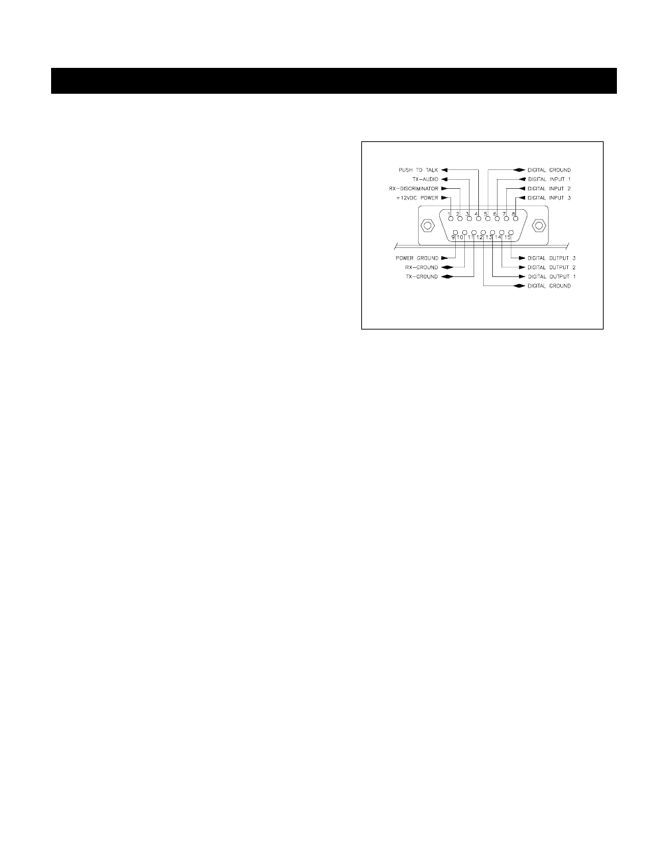
The diagram on the right is an end view of the radio interface
connector on your RI-200. Use the supplied DB-15 male
connector for making all connections to the controller.
2.1
PROPER TECHNIQUES FOR QUALITY REPEATER AUDIO
Obtaining good audio in any repeater is based on understanding the design of the equipment. The audio in all frequency
modulation (FM) transmitters or phase modulation (PM) transmitters have what is known as audio pre-emphasis. Pre-
emphasis means that with increasing audio frequency the amount of the modulation will increase. The reverse is performed
in all FM receivers and is called de-emphasis. The RI-200 was designed to operate with flat audio response from the repeater
receiver and transmitter. This means that no de-emphasis and pre-emphasis of the audio is performed on the repeater or
controller. This leaves all of the emphasis filtering in the user's radio. The RI-200 controller does include a low pass filter
that rolls off the very high audio frequency content to prevent adjacent channel splatter. The ideal interface between the RI-
200 and a FM modulator is when a varactor diode is directly driven. However the RI-200 does have a de-emphasis filter that
can be turned on for those applications where you may need to interface to a modulator with pre-emphasis. It is not advisable
to drive the microphone input on the transmitters. Most transmitters have significant audio shaping, compensating for the
microphone response and other characteristics. The input connections to the RI-200 must be connected directly to the
receiver’s discriminator for the squelch to work properly. On some receivers this connection can be made to the squelch
circuit input.
Besides audio frequency response, you should consider the audio amplitude levels to and from the controller. If the levels to
and from the repeater are small, it may be valuable to use shielded cable. We recommend shielded cables at all times. Use
large signal levels whenever possible. On the other hand, do not let the audio signal get large enough where clipping occurs
in any stage of the controller, the receiver, or the transmitter. The RI-200 repeater controller has a built in audio level meter
for setting the RX input level. See section 3.4 for more details on adjusting the audio levels in the controller. Consider and
practice the above and you will have repeater audio that you and your repeater users will be proud of.
2.2
POWER SUPPLY CONNECTIONS
The RI-200 operates on 12 volts DC nominal. The DC source voltage must be between 10 and 15 VDC. The controller
typically draws 50 ma without the status LED’s turned on. Connect the +12v to J1 pin 1. Connect J1 pin 9 to ground or the
12 V return side of the power supply. The repeater builder may elect to incorporate an on/off power switch on the +DC side.
Most repeater owners switch the AC primary side of the power supply. The RI-200 repeater controller connection to the
power supply must be over current protected. Use of a one ampere fuse should be the largest capacity considered in your
installation. A 250 ma fuse is best. When connected properly, the green LED on the status LED display will light when the
power is applied and the system enable command is on.
RADIO INTERFACE CONNECTOR