Pacific Research Solutions RI-200 User Manual
Page 8
Pacific Research Solutions
RI-200 User Manual
Page 7
1.3
INSTALLING THE RI-210 REPEATER CONTROLLER
Skip to the next section if you are not installing the RI-210 into a VX-5000 repeater.
1.
Start by removing the four screws holding the top cover on the Vertex repeater.
2.
Install the Vertex programming cable and a dummy load on the TX ANT connector.
3.
Connect power to the repeater and run the Vertex programming software that came with the vertex repeater.
4.
Select the “CLONE” mode and use “F3” to copy the current repeater configuration to the program.
5.
Go into the “Timer” menu and disable all of the “REPEATER’ and “BASE” timers.
6.
Go into the “Setup” menu and set the “Mode” to “Duplex”, the “Beep” to “Disable” and “Hang” to “Quiet”.
7.
Because the RI-210 has its own CTCSS/DCS decoder, you will need to disable the Vertex CTCSS decoder. Last, go into
the “Option” menu and disable the Vertex CTCSS tone decode. In some older models of the repeater, you will need to
unplug the optional Vertex CTCSS decoder assembly.
8.
Save these new values to the repeater by using “F4” key.
9.
Disconnect the power and programming cable from the repeater
10.
Place the RI-210 in the slot between the receiver and the exciter. The telephone jack should be located on the side closest
to the power supply or RF power amp.
11.
The mounting holes in the RI-210 should line up with the mounting tabs in the Vertex repeater. The RI-210 is held in
place by the two screws that were supplied. The bottom of the RI-210 circuit board should line up with a card edge
bracket in the bottom of the Vertex repeater.
12.
There are four cables used to connect the RI-210 controller to the Vertex repeater. On the Vertex Control 2 board, you
need to unplug the two pin connector plug J2007 and plug it into the two pin connector on the RI-210.
13.
Unplug the four pin connector J2006 and plug it into the four pin connector on the RI-210.
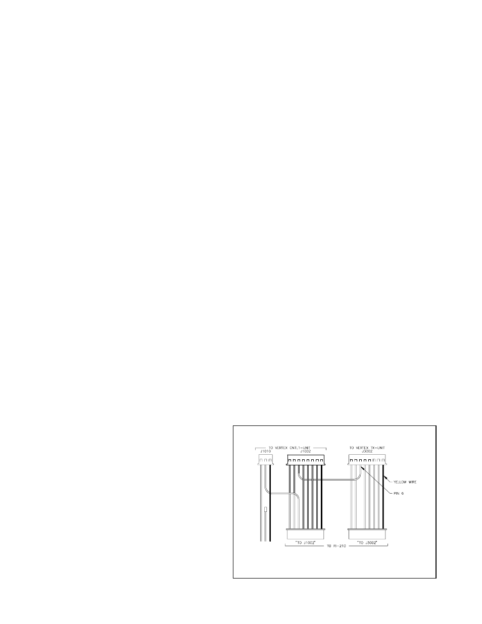
14.
Follow the diagram below. From the Vertex Control 1 board you need to unplug connector J1002. This connector has 8
wires going to it and the yellow wire is pin 1. Remove pin 6 contact from the housing. This can be done by using the tip
of a x-acto knife to lift up on the plastic finger that holds the contact in the housing and remove the contact.
15.
On the 8 pin cable supplied with the RI-210 controller, you will notice one of the housing is missing a contact at pin 6.
Take the contact that you just removed and plug it into this housing.
16.
Plug your connector housing with the missing contact, into the connector on the RI-210 marked “TO J3002.
17.
Plug in the other connector housing with a free wire and contact into the connector on the RI-210 marked “T0 J1002”.
18.
Plug in the last connector where you just installed a contact, into the Vertex controller where you removed the 8 pin cable
in step 14.
19.
Un-plug the 3 pin connector on the Vertex Control 1 board labeled “J1010”.
20.
Remove the center contact from this housing. This can be done by using the tip of an x-acto knife to lift up on the plastic
finger that holds the contact in the housing and remove the contact
21.
Plug the extra wire and contact coming from the RI-210 8 pin connector into the center position of this 3 pin plug.
Reinstall the 3 pin plug into the Vertex Controller.
22.
Insulate the last free contact so that it will not short out on anything.
23.
On the Vertex repeater “ACC” connector, connect pin 13 “base” to pin 1 “ground”, use the supplied DB25 connector.
24.
Because the RI-210 is designed to function directly in
the Vertex repeater, all input and output audio levels
have been preset, however the receiver and
transmitter audio levels and squelch gain may need
minor adjustments. See Section 3.4 for details on
this procedure.
25.
Use the potentiometer on the top of the “TX UNIT”
to adjust the DCS deviation.
26.
Because the RI-210 controller may key up the
repeater at any time. Make sure that you install a
dummy load on the TX ANT connector before you
reconnect power to the repeater for testing.
The repeater controller and telephone interconnect is now
functional with the factory default commands, features,
and messages. This allows operation of your new
repeater within minutes of installation.
VERTEX INTERNAL CABLE MODIFICATIONS