Function, Hardware orientation – RGBLink VSP 628S User Manual User Manual
Page 32
2.
Hardware Orientation
VSP 628S Front Panel
VSP 628S User Manual 32
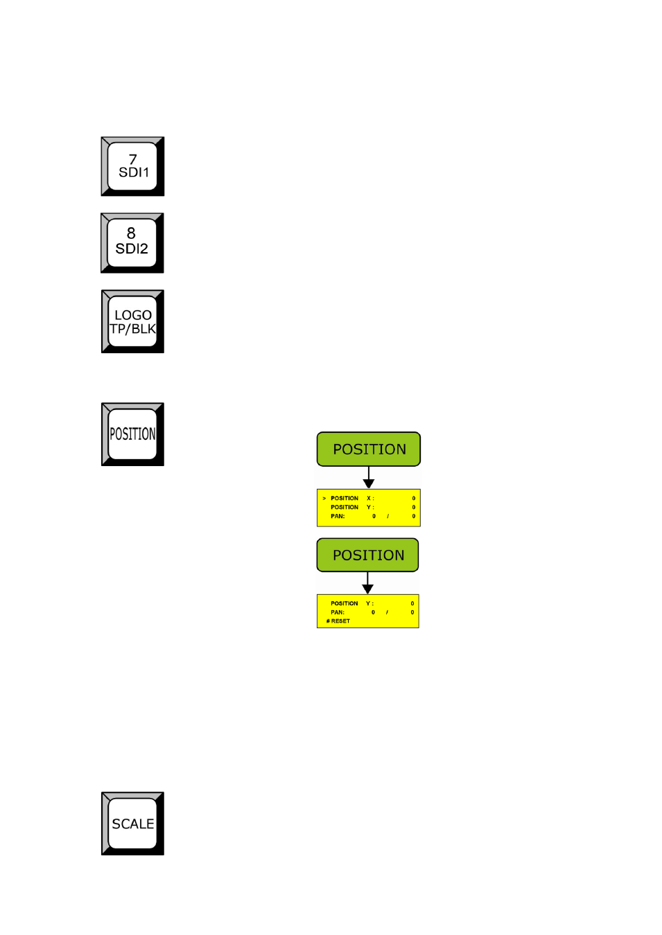
SDI1 input selection Button, its LED light turns on, output will be switched
to this channel;
SDI2 input selection Button, its LED light turns on, output will be switched
to this channel;
LOGO, test pattern, BLK button, its LED light turns on,
factory set is default
for the test pattern. Test pattern can be set and selected from LCD panel,
press the button again, to disable pattern.
Function
Image position adjustment key, press the key, LED prompts activation:
Default will active to set Position X, and push the key again, will active to
set Position Y. Use left-right knob to adjust X and Y coordinates, and push
SEL key to confirm.
Choose PAN to adjust X and Y coordinates synchronously, select RESET
to reset the changed values.
Image size adjustment key, press the key, LED prompts activation: