Scotsman CME256 AutoIQ User Manual
Page 54
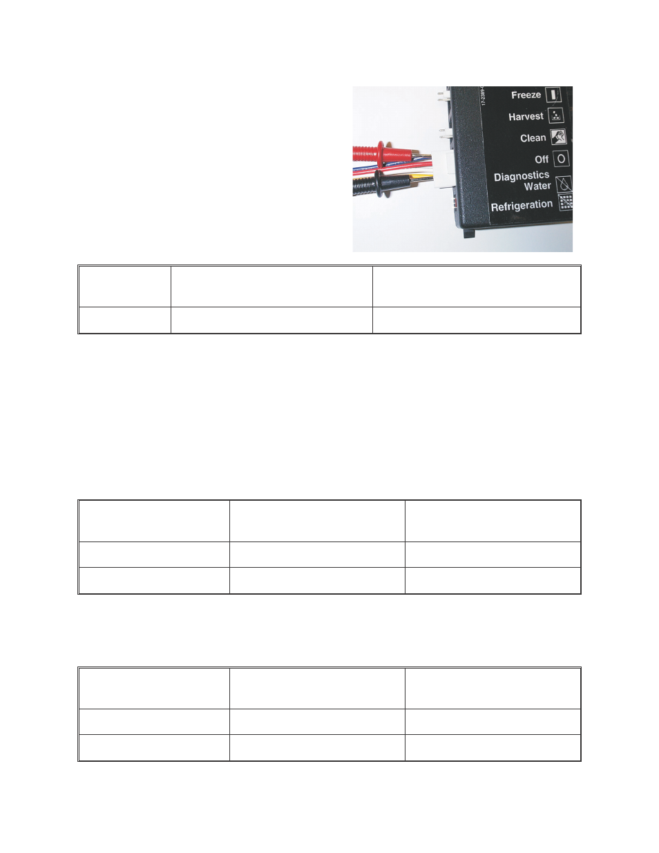
Harness Connected Voltage (DC)
6. At the controller, measure the voltage
between the top and bottom pins on
connection #2. This should be between the
ranges in the table below. If it outside this
range there is a problem in the sensor and it
should be changed out. If it is within this
range, proceed to the next step.
Yellow (bottom) - Black Housing
Controllers
Yellow (bottom) - Blue Housing
Controllers
Blue (top)
2 to 3.5 VDC
.4 to 2.0 VDC
7. Place negative voltmeter probe on the bottom terminal (yellow wire). Place the other
on the one just above it (terminate freeze sender - white wire). Move the float stem/stick
up and down and note the voltage changes. There should be a significant change
between when it is blocked to when it is not blocked. If there is NO change, the sensor
may be dirty or has failed. Remove the dust cover from the sensor to clean it.
Note: The sensor must be properly reassembled. When looking at the terminals of the
sensor, they must be in the lower right corner. If they are in the upper left remove the
sensor’s dust cover and reverse the board. Later models have an UP arrow on the right
side of the circuit board.
Yellow (bottom) Black
Housing Controllers
Yellow (bottom) Blue
Housing Controllers
White - Blocked
5 VDC
about 5 VDC
White - Unblocked
<1 VDC
less than when blocked
8. With the voltmeter probe still on the bottom terminal (still in connection #2), place the
other one on the second pin from the top (sump full sender - red wire). Move the float
stick up and down, note the changes in voltage. It should react the same as in step 7.
Yellow (bottom) Black
Housing Controllers
Yellow (bottom) Blue
Housing Controllers
Red - Blocked
5 VDC
about 5 VDC
Red - Unblocked
<1 VDC
less than when blocked
9. If all voltages check out, there is nothing wrong with the sensor or the voltage it
receives from the controller.