Space Ray LTU Series Two Stage User Manual
Page 13
Form #42710010
May 2013
-11-
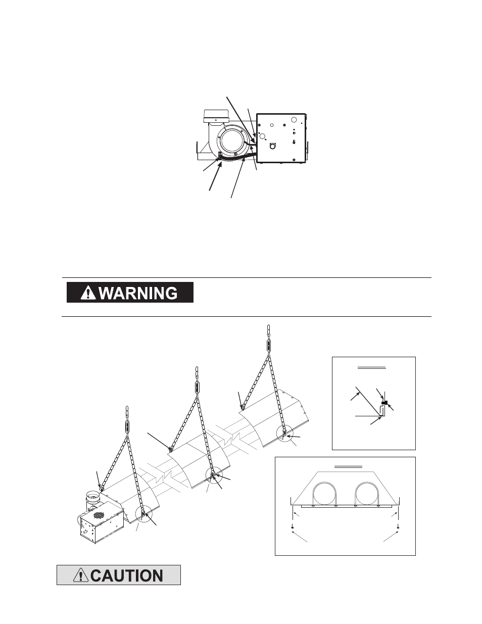
7. Slip the plastic vacuum air tube over the 1/4” O.D. aluminum tube end of the draft inducer and the air
switch probe in the control box. The air tube should be shortened to prevent a downward sag which could
allow condensation build-up in the tube.
8. Insert motor lead wires through the strain relief bushing of the control box and connect black lead wire to
Relay Terminal 3 and white lead wire to L2 of the 2-pole terminal block. Refer also to the wiring diagram in
Section 13.0).
Plastic Vacuum
Air Tube
1/4 O.D.
Tube
Motor Leads
(to L1 and L2 of
the terminal block)
Strain Relief
Bushing
7
8
9. Reflectors should overlap 3” in the middle and must be secured by sliding speed clips on the reflector edges.
One speed clip is required for each side of the reflector.
10. Fasten the first reflector to the tube support/hanger bracket with (2) #10 sheet metal screws according to
Detail “A”. Mount the sliding reflector clamps (#42769010) per Reflector Clamp Installation (Detail “B”) on
all tube support/hanger brackets. Make sure the reflector can slide under the clamp during heater operation.
The reflector clamps MUST be
The reflector clamps MUST be
The reflector clamps MUST be
The reflector clamps MUST be installed per reflector
installed per reflector
installed per reflector
installed per reflector
clamp installation detail which allows the reflector to
clamp installation detail which allows the reflector to
clamp installation detail which allows the reflector to
clamp installation detail which allows the reflector to
slide under the clamp during heater operation.
slide under the clamp during heater operation.
slide under the clamp during heater operation.
slide under the clamp during heater operation.
9
10
10
10
10
10
Tube Support &
Hanger Bracket
Reflector
Clamp
Reflector
Clamp
Screw
Reflector Clamp Installation
DETAIL A
Fasten screws to tube
hanger/support bracket and reflector
(only the tube support/hanger
bracket closest to the control end)
#10 x 1/2 SHEET METAL
SCREWS (QTY - 2)
10
See Detail A & B
DETAIL B
See Detail B
See Detail B
Do not relocate the tube support/hanger bracket at the control box end of
Do not relocate the tube support/hanger bracket at the control box end of
Do not relocate the tube support/hanger bracket at the control box end of
Do not relocate the tube support/hanger bracket at the control box end of
the heater. This will increase the weight on t
the heater. This will increase the weight on t
the heater. This will increase the weight on t
the heater. This will increase the weight on the emitter tube and can result
he emitter tube and can result
he emitter tube and can result
he emitter tube and can result
in premature tube failure.
in premature tube failure.
in premature tube failure.
in premature tube failure.