4) ignition system checks – Space Ray LTU Series Two Stage User Manual
Page 36
Form #42710010
-34-
May 2013
21.4) IGNITION SYSTEM CHECKS
TO CHECK
TO CHECK
TO CHECK
TO CHECK IGNITION CABLE
IGNITION CABLE
IGNITION CABLE
IGNITION CABLE....
a. Make sure that the ignition cable does not touch any metal surface.
b. Make sure that connections to the stud terminal and the igniter/sensor are clean and tight.
c. Make sure that the ignition cable provides good electrical continuity.
TO CHECK
TO CHECK
TO CHECK
TO CHECK IGNITION SYSTEM GROUNDING
IGNITION SYSTEM GROUNDING
IGNITION SYSTEM GROUNDING
IGNITION SYSTEM GROUNDING....
(Nuisance shutdowns are often caused by a poor or erratic ground.) A common ground is required for the
module, igniter, flame sensor and main burner.
a. Check for good metal-to-metal contact between the igniter bracket and the main burner.
b. Check the ground lead from the GND (BURNER) terminal on the module to the igniter bracket. Make sure
connections are clean and tight. If the wire is damaged or deteriorated, replace it.
c. Replace igniter/sensor with factory replacement part if insulator is cracked.
TO CHECK
TO CHECK
TO CHECK
TO CHECK SPARK IGNITION CIRCUIT
SPARK IGNITION CIRCUIT
SPARK IGNITION CIRCUIT
SPARK IGNITION CIRCUIT....
▲WARNING:
▲WARNING:
▲WARNING:
▲WARNING: The ignition circuit generates a 20,000 Volt open circuit and electrical shock can result.
a. Check ignition cable.
b. Check external fuse located inside the control box.
c. Verify power (24V) at module input terminals and output terminal to gas valve.
d. Replace spark module if fuse and power are OK.
IGNITION MODULE DIAGNOSTICS
IGNITION MODULE DIAGNOSTICS
IGNITION MODULE DIAGNOSTICS
IGNITION MODULE DIAGNOSTICS
(Fenwal #35
(Fenwal #35
(Fenwal #35
(Fenwal #35----6087J1
6087J1
6087J1
6087J1----034 module only)
034 module only)
034 module only)
034 module only)
The LED
LED
LED
LED located on the ignition module will flash ON
ON
ON
ON for ¼ second, then OFF
OFF
OFF
OFF for ¼ second during a fault
condition. The pause between fault codes is 3 seconds.
LED Indication
Error Mode
Steady On
Internal Control Fault
2 Flashes
Flame Sense Fault
3 Flashes
Ignition Lockout
TO CHECK FLAME SENSOR CIRCUIT
TO CHECK FLAME SENSOR CIRCUIT
TO CHECK FLAME SENSOR CIRCUIT
TO CHECK FLAME SENSOR CIRCUIT
(Fenwal #35
(Fenwal #35
(Fenwal #35
(Fenwal #35----6087J1
6087J1
6087J1
6087J1----034 module only)
034 module only)
034 module only)
034 module only)
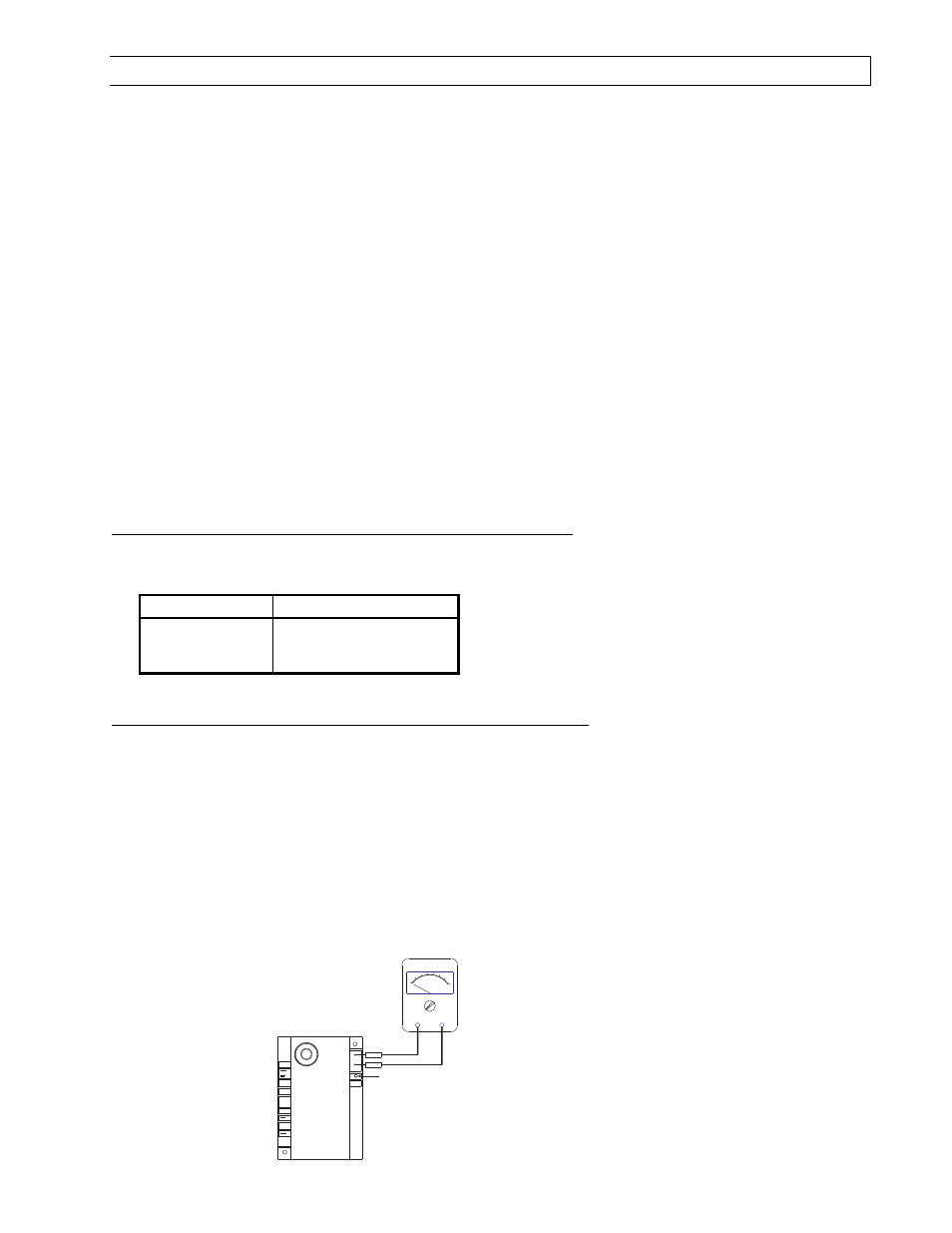
The flame current is the current that passes through the flame from the sensor to the ground. The
minimum flame current necessary to keep the system from lockout is 0.7
0.7
0.7
0.7 micro-amps.
a. To measure the flame current, connect an analog DC micro-ammeter to the FC
FC
FC
FC---- and FC+
FC+
FC+
FC+ terminals per
diagram. The meter should read 0.7
0.7
0.7
0.7 micro-amps or higher when the burner is running full on.
b. If the meter reads below zero
zero
zero
zero, the meter leads are reversed. Disconnect power and reconnect the meter
leads for proper polarity.
c. Remove micro-ammeter. Return system to normal operation.
MULTIPURPOSE METER
USE
MICROAMP
SCALE
BLACK (-)
RED (+)
LED Display
VALVE
GND
(BURNER)
FC-
FC+
VALVE
25V
Ignition Module - Alternate
(Fenwal #35-6087J1-034)