0) control component location – Space Ray LTU Series Two Stage User Manual
Page 28
Advertising
Form #42710010
-26-
May 2013
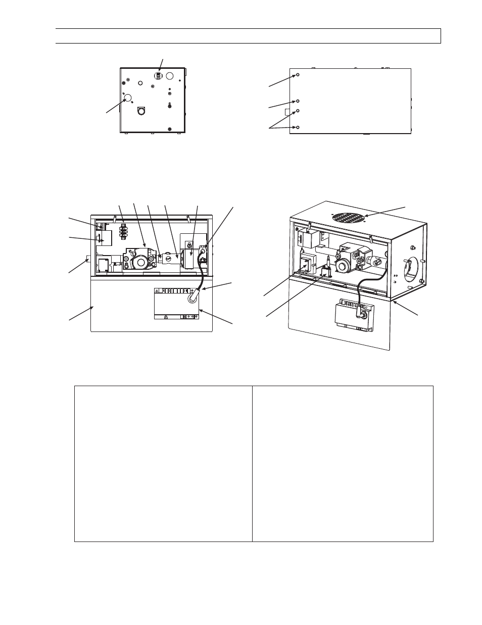
18.0)
CONTROL COMPONENT LOCATION
1
2
3
6
5
4
8
7
9
10
12 14 16
17
18
19
20
21
1
Cabinet Assembly
2
Air Inlet Plate
3
Sight Glass
4
Monitoring Light, Green
5
Monitoring Light, Red
6
Monitoring Light, Amber (2)
7
Access Panel
8
Restrainter Nipple, 5 Long
9
Terminal Block and Shield
10
Air Switch
11
Relay
12
Gas Valve
13
3-Pole Terminal Block
14
Orifice
15
Thermostat Connection Block
16
Main Burner
17
Burner Clamp
18
Spark Electrode
19
Ignition Cable
20
Ignition Module
21
Transformer (120/24 VAC)
11
13
15
NOTE:
NOTE:
NOTE:
NOTE: Access panel
Access panel
Access panel
Access panel only
only
only
only opens
opens
opens
opens to
to
to
to 90
90
90
90°°°°....
Advertising
This manual is related to the following products: