The rear panel, Power connections – Thinklogical Remote Power Distribution Unit 4/4 Manual User Manual
Page 8
®
PDU 4/4 Product Manual September, 2014
Page 7
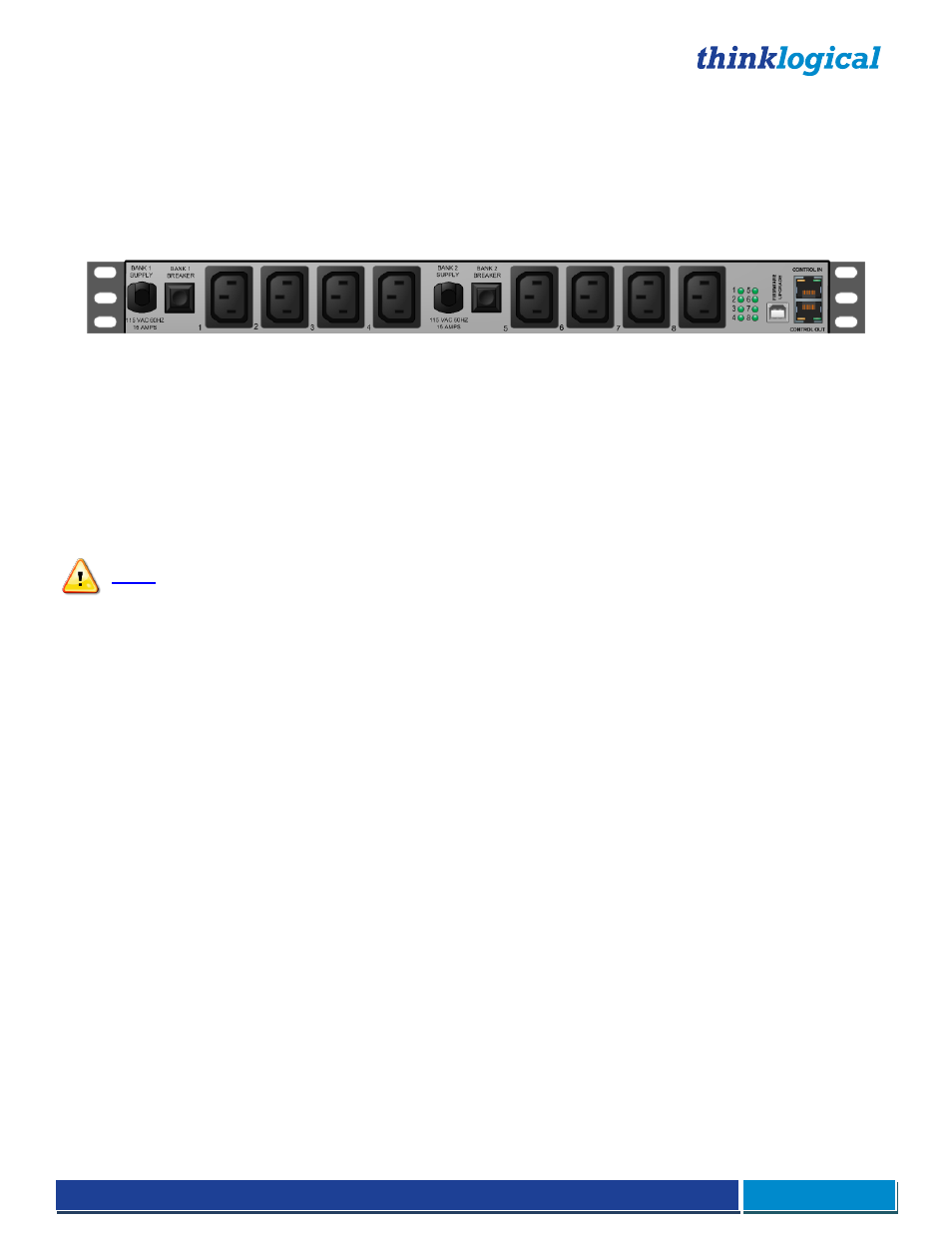
The Rear Panel
Power Connections
The rear panel features two outlet banks. Each bank consists of (1) AC Input Power Cord, (1) Power
Switch/Circuit Breaker, and (4) AC Power Outlets.
Bank 1 provides AC output power to Ports 1 through 4
Bank 2 provides AC output power to Ports 5 through 8
Domestic
Each AC Input Power Cord is outfitted with a NEMA 5-15P plug for all US/Domestic orders. Each Bank also
has a 15 Amp Power Switch/Circuit Breaker that supplies AC power to the bank of four switched outlets and
to the internal power supply. If only one Power Switch/Circuit Breaker is turned on, the internal, redundant
power supply will power the PDU and that one bank will provide AC output. If both banks are off, all outputs will
be off.
The four switched AC outlets per bank are NEMA 5-15R, nominal-115VAC power outlets. Bank 1 consists of
Ports/Outlets 1 through 4 and Bank 2 consists of Ports/Outlets 5 through 8. Each outlet is independently
controlled and can switch up to 10 Amperes. However, the total power draw for each bank of 4 outlet ports
must not exceed 15 Amperes.
Note: The total power draw for each bank of 4 outlet ports must not exceed 15 Amperes.
The two internal power supplies that are used to power the PDU system are redundant. This feature will allow
the unit to maintain power in the event of a DC Power Supply failure. Upon recovery from a power failure, the
PDU will return all Ports to the same state they were in prior to the power loss.
International
The International version of the PDU 4/4 has the same features as the Domestic version except for the
following:
Each of the (2) AC Input Power Cords are outfitted with an EU power plug.
Each of the (8) Switched AC Outlets are outfitted with a universal power outlet.
Status LEDs
The LEDs on the rear panel correspond to each of the (8) Switched AC Outlets. (For example, LED 1 shows
the status of Outlet/Port 1, LED 2 shows the status of Outlet/Port2, etc.) When the status light of an Outlet/Port
is
green
, the Outlet/Port has power.
USB Firmware Upgrade Port
There is a USB-B connector on the rear panel of the PDU for firmware upgrades. Firmware updates are
through a USB cable and an application that runs on a Windows (2000, XP, or Vista) PC.
Please visit http://ftp.thinklogical.com/ftp/visualization/updates for updates and instructions.
Serial Interface
The PDU 4/4 features (2) RJ45 serial connectors, labeled CONTROL IN and CONTROL OUT, on the rear
panel. If cascading multiple PDU units, the first PDU will be connected to the controlling terminal using the
CONTROL IN port. The CONTROL OUT port will be connected to the CONTROL IN port of the next unit using
a straight-through RJ45 cable, and so on.