Installation, Secure console servers, Port setting for your terminal device – Thinklogical Remote Power Distribution Unit 4/4 Manual User Manual
Page 9: Cascading the pdu chassis, Box ids
®
PDU 4/4 Product Manual September, 2014
Page 8
Installation
The PDU is designed to stand alone or to connect to a
Thinklogical Secure Console Server
®
. Each device port
of the Secure Console Server is a compatible RS-232
serial port designed to connect to the PDU’s CONTROL
IN port. The PDU is installed by first connecting to the
device port using commands in the Console Server, then
once connected, by using PDU commands.
Refer to the Console Server Manual for Console Server
information (available online at
Secure
Console
Servers
SCS320 Secure Console Server
100-240V -, 0.5A, 50/60 Hz
T2A, 250 VAC
CAUTION!
Replace with same type and rating fuse.
1 2 3 4 5 6 7 8
9 10 11 12 13 14 15 16
17 18 19 20 21 22 23 24
25 26 27 28 29 30 31 32
PORTS
NETWORK
CONSOLE
www.thinklogical.com
Use an Ethernet cable to connect the desired device port to the PDU's CONTROL IN port. The connection is made
with the device port configured as follows:
Port Setting for your Terminal Device
If your switch does not have a dedicated 'Power Manager' port, you may configure a serial port to the
following settings:
Configure an RS-232 serial port as a DTE (Data Terminal Equipment) port.
Configure the port for 9600 baud, 8 data bits, No Parity, 1 Stop Bit.
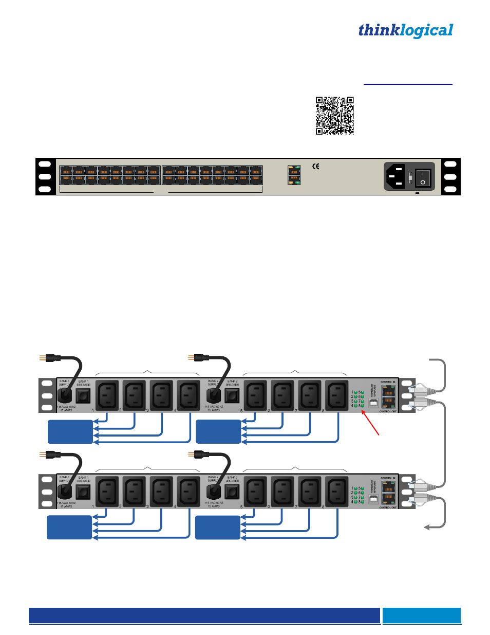
Cascading the PDU Chassis
If more than eight switched AC Power ports are required, the PDU 4/4 configuration can be expanded by daisy-
chaining up to sixteen (16) PDU 4/4 chassi
s. The first PDU 4/4 assumes the “Master” role, with the Master PDU 4/4’s
CONTROL OUT Port connected to the next chassis CONTROL IN Port by an RJ45 serial cable.
CPU or Terminal Device
To PDU 4/4 Units 3...16
Standard AC voltage OUT
(Unit 2 Bank 1)
PDU 4/4 Unit 1
PDU 4/4 Unit 2
Unit 1 Bank 1
Devices
Unit 2 Bank 1
Devices
Unit 2 Bank 2
Devices
Unit 1 Bank 2
Devices
Individual port status LEDs
Domestic PDU 4/4 Configuration
Standard AC voltage OUT
(Unit 2 Bank 2)
Standard AC voltage OUT
(Unit 1 Bank 1)
Standard AC voltage OUT
(Unit 1 Bank 2)
Box IDs
Units are only assigned master or slave status after logging in. Before log in, all boxes display a box ID of 0. The first
box assumes the Master box ID of 1.
Additional PDU 4/4 boxes are designated a “Slave” status and are