Testing, Introduction, Indicators – Verilink AS420 (34-00294) Product Manual User Manual
Page 21: Chapter 3 testing, Esting
Advertising
T e s t i n g
13
C
H A P T E R
3
C
HAPTER
3
T
ESTING
Introduction
This chapter describes the diagnostic and test features of the AS420. The unit
is controlled manually using rear panel DIP switches (the DIP switches are
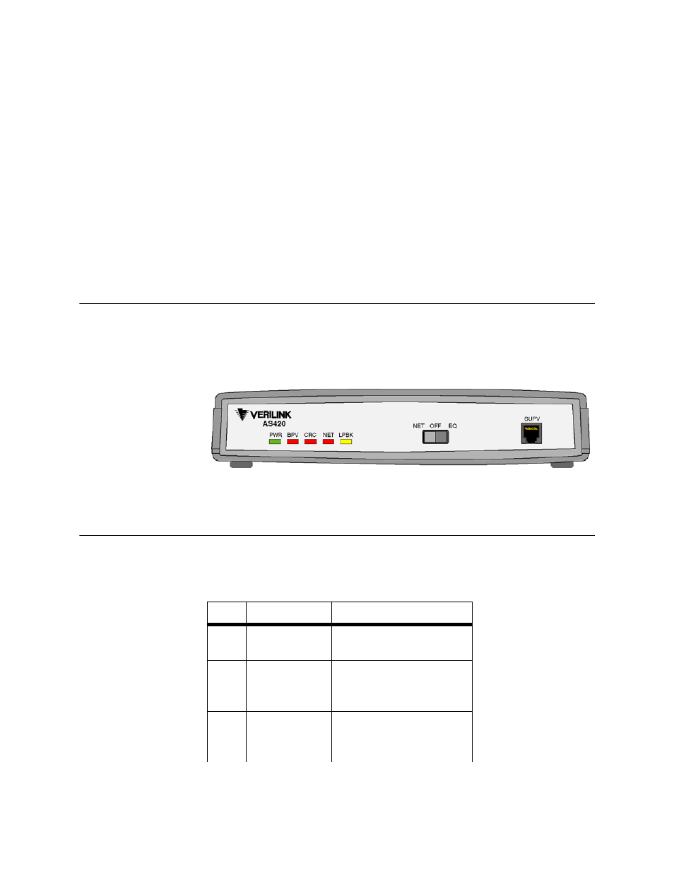
discussed on page 9). The front panel indicators and switch are shown in
Figure 3.1 and described below.
Figure 3.1
AS420 Front Panel
Indicators
The front panel indicators shown in Figure 3.1 convey major alarm conditions
and looping status.
Table 3.1
AS420 Front Panel Indicators
LED
Condition
Description
PWR
Off
Solid
Power off.
Power is applied to the unit.
BPV
Off
Flashing Red
Solid Red
No errors.
Intermittent BPV errors.
Continuous BPV errors.
CRC
Off
Flashing Red
Solid Red
No errors.
Intermittent CRC-4 errors.
Continuous CRC-4 errors.
Advertising