Menu layout, Assigning the diu to a csu – Verilink DIU 2131 (880-502765-001) Product Manual User Manual
Page 16
Configuration Menu
3-2
Verilink User Manual
Menu Layout
The fields in the
DIU 2131 Configuration/Diagnostic Menu
can be
viewed as groups of related functions.
The small letter
p
to the right of most commands is a placeholder
for the number of the port you want to access. For example, if you
want to enable the loopbacks for Port 1, enter “
E1”
. If you want to
enable loopbacks for Port 2, enter
“E2”
.
The upper portion of this display lists the configuration commands
and current DIU configuration settings. The lower portion lists the
diagnostic commands for the DIU 2131.
The screen above show Channels 1-12 assigned to Port 1 and
Channel 15 assigned to Port 2. It also shows the options available
after the user has entered the mode (M) command for Port 2.
The statistics area provides the following information:
The handshake control signals display area fields change to show
which ports, if any, are force high.
Assigning the
DIU to a CSU
This assignment establishes the data path between the DIU and the
associated CSU using the data bus previously assigned in the CSU
Configuration Menu.
CAUTION
Any time the DIU bus assignment is changed in a CSU, all DIUs assigned to
that CSU need to be reassigned. To reconfigure them correctly, you must
re-enter the shelf and slot number for each DIU, even if the correct
numbers already appear on the screen.
To assign a DIU to a CSU in the node:
What type of interface is on Port 1 and Port 2,
DIU 2131 firmware and hardware revision numbers
Whether the battery power is “OK” or “LOW”
respectively
hich data bus you selected in the CSU Configuration Menu
Statistics
Statistics
Statistics
Statistics
FW/HW Rev
FW/HW Rev
FW/HW Rev
FW/HW Rev
1.0/0.8
1.0/0.8
1.0/0.8
1.0/0.8
Battery
Battery
Battery
Battery
OK
OK
OK
OK
DTE Intf
DTE Intf
DTE Intf
DTE Intf
V.35/RS-232
V.35/RS-232
V.35/RS-232
V.35/RS-232
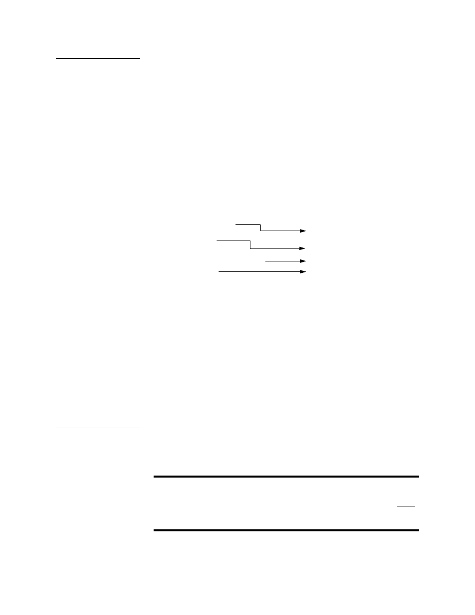
Lead Toggles
DTR
DSR
RTS
CTS
DCD
Forced Ports
1/2
-/-
-/-
-/-
-/-
In this example, DTR is forced high for Ports 1 and 2. None of the other
signals are forced for any port.