Setting diu up for multiplexing, Diu 2131 configuration/diagnostic menu – Verilink DIU 2131 (880-502765-001) Product Manual User Manual
Page 17
Configuration Menu
Verilink User Manual
3-3
1. Select a related CSU, type
“C”
on the prompt line of the
DIU
2131 Configuration/Diagnostic Menu
.
2. Press the
E
NTER
key. A new prompt line will appear requesting
a shelf number.
3. Enter the number of the shelf you wish to access, and press
E
NTER
. A second prompt line will appear, requesting you to
enter the slot number of the related CSU.
Setting DIU up
for Multiplexing
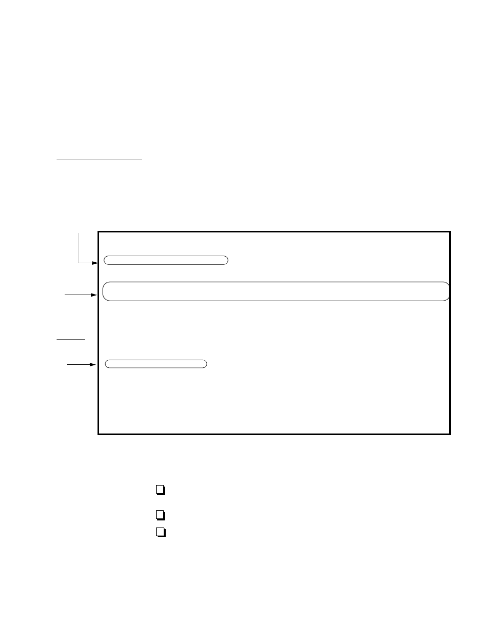
Figure 5-2 shows how to set up the DIU 2131 configuration screen
for muxing.
Figure 3-2 DIU 2131 Configuration for Mux Mode
Since the Craft interface does not check for errors when you save a
configuration, validate the following:
Each DIU is assigned to the proper CSU (
CSU
command in DIU
menu).
The mode (
56k
or
64k
) is correct for Port 1.
The channels used on the near end match those on the far end
in a point-to-point circuit. For example, if the near end uses
DS0s 1-6, the far end must also use DS0s 1-6. If you’re going
through a DACS, this may not apply.
--- DIU 2131 CONFIGURATION/DIAGNOSTIC MENU ---
--- DIU 2131 CONFIGURATION/DIAGNOSTIC MENU ---
--- DIU 2131 CONFIGURATION/DIAGNOSTIC MENU ---
--- DIU 2131 CONFIGURATION/DIAGNOSTIC MENU ---
C) CSU [ 1,1 ]
C) CSU [ 1,1 ]
C) CSU [ 1,1 ]
C) CSU [ 1,1 ]
T) timing source CSU
T) timing source CSU
T) timing source CSU
T) timing source CSU
chnl 01 02 03 04 05 06 07 08 09 10 11 12 13 14 15 16 17 18 19 20 21 22 23 24
chnl 01 02 03 04 05 06 07 08 09 10 11 12 13 14 15 16 17 18 19 20 21 22 23 24
chnl 01 02 03 04 05 06 07 08 09 10 11 12 13 14 15 16 17 18 19 20 21 22 23 24
chnl 01 02 03 04 05 06 07 08 09 10 11 12 13 14 15 16 17 18 19 20 21 22 23 24
Dp)port 01 01 01 01 01 01 01 01 01 01 01 01 .. .. 02 .. .. .. .. .. .. .. .. ..
Dp)port 01 01 01 01 01 01 01 01 01 01 01 01 .. .. 02 .. .. .. .. .. .. .. .. ..
Dp)port 01 01 01 01 01 01 01 01 01 01 01 01 .. .. 02 .. .. .. .. .. .. .. .. ..
Dp)port 01 01 01 01 01 01 01 01 01 01 01 01 .. .. 02 .. .. .. .. .. .. .. .. ..
Lead Toggles DTR) DSR) RTS) CTS) DCD)
Lead Toggles DTR) DSR) RTS) CTS) DCD)
Lead Toggles DTR) DSR) RTS) CTS) DCD)
Lead Toggles DTR) DSR) RTS) CTS) DCD)
Forced Ports -/- -/- -/- -/- -/-
Forced Ports -/- -/- -/- -/- -/-
Forced Ports -/- -/- -/- -/- -/-
Forced Ports -/- -/- -/- -/- -/-
Port 1 Port 2 Statistics
Port 1 Port 2 Statistics
Port 1 Port 2 Statistics
Port 1 Port 2 Statistics
Mp) mode 64K 19.2K FW/HW Rev...1.3/0.8
Mp) mode 64K 19.2K FW/HW Rev...1.3/0.8
Mp) mode 64K 19.2K FW/HW Rev...1.3/0.8
Mp) mode 64K 19.2K FW/HW Rev...1.3/0.8
Sp) scram/hdlc inv N/N N/N Battery.....OK
Sp) scram/hdlc inv N/N N/N Battery.....OK
Sp) scram/hdlc inv N/N N/N Battery.....OK
Sp) scram/hdlc inv N/N N/N Battery.....OK
Kp) clocking ST ST DTE Intf....V.35/RS-232
Kp) clocking ST ST DTE Intf....V.35/RS-232
Kp) clocking ST ST DTE Intf....V.35/RS-232
Kp) clocking ST ST DTE Intf....V.35/RS-232
Gp) LOS lead NONE NONE Data bus....A
Gp) LOS lead NONE NONE Data bus....A
Gp) LOS lead NONE NONE Data bus....A
Gp) LOS lead NONE NONE Data bus....A
Ep) enable loop YES YES Tp) test and monitor BEC
Ep) enable loop YES YES Tp) test and monitor BEC
Ep) enable loop YES YES Tp) test and monitor BEC
Ep) enable loop YES YES Tp) test and monitor BEC
Np) near loopback OFF OFF Pp) monitor leads and status
Np) near loopback OFF OFF Pp) monitor leads and status
Np) near loopback OFF OFF Pp) monitor leads and status
Np) near loopback OFF OFF Pp) monitor leads and status
Fp) far loopback OFF OFF A) Alarm Enable......NO
Fp) far loopback OFF OFF A) Alarm Enable......NO
Fp) far loopback OFF OFF A) Alarm Enable......NO
Fp) far loopback OFF OFF A) Alarm Enable......NO
[1,2] DIU 2131 >
[1,2] DIU 2131 >
[1,2] DIU 2131 >
[1,2] DIU 2131 >
If the CSU is in a different shelf, you will
need a data bus extension kit. Remember,
you must re-enter the CSU if you make bus
change
.
When using
consecutive
channels, 64K
Mode will
require B8ZS
in the CSU’s
network (
F
) line
coding.
Unless the
signal
is going through
a DACS,
channel
assignments
must match at
both ends of