Quad t1 to imux, Quad t1 to imux -6, Figure 2-3 – Verilink IMUX (880-503137-001) Product Manual User Manual
Page 20
Advertising
Quick Set-Up
2-6
Verilink IMUX User Manual
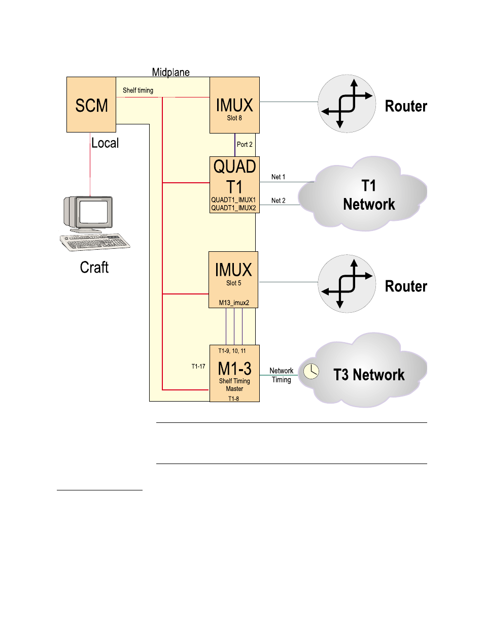
Figure 2-3 Example Configurations
NOTE: The assumption is made that the ports of the IMUX (slots 5
and 8), QUAD T1 and M1-3 modules have been placed in
service and configured. Always place ports in service and
configure them before building circuits.
QUAD T1 to IMUX
From the QUAD T1 Main Menu, type "B" to access the Circuit Build
function of the SCM. The Circuit Manager Menu displays, as shown
in
.
Advertising
See also other documents in the category Verilink Computer hardware:
- 1061 T1 Multicast (34-00268) Product Manual (18 pages)
- 2010 (34-00204) Product Manual (15 pages)
- 1558A (34-00228) Product Manual (39 pages)
- 1558D (34-00255) Product Manual (42 pages)
- 210 (34-00196) Product Manual (9 pages)
- 2000 (34-00182) Product Manual (58 pages)
- 300 (34-00199) Product Manual (9 pages)
- 2048 (34-00179) Product Manual (33 pages)
- 400 (34-00222) Product Manual (9 pages)
- 2100 (34-00187) Product Manual (19 pages)
- 7200p Series IAD (34-00334.B) Product Manual (311 pages)
- APS 2000 T1 Line Protection (880-502411-001) Product Manual (87 pages)
- AS200 (896-502379-001) Product Manual (112 pages)
- AS420 (34-00294) Product Manual (28 pages)
- AS56/56Plus (896-502588-001) Product Manual (130 pages)
- 9000 Series (34-00271) Product Manual (440 pages)
- AS2000: The Basics (880-502981-001) Product Manual (179 pages)
- Access Manager 2000 (896-502037-001) Product Manual (400 pages)
- ConnecT 56K DSU (896-502110-001) Product Manual (88 pages)
- AS4000 (34-00244) Product Manual (210 pages)
- C150 (880-502893-001) Product Manual (135 pages)
- Craft Interface (No Part Number) Product Manual (8 pages)
- DDS Lite (34-00295.C) Product Manual (19 pages)
- DCSU 2911 (880-502647-001) Product Manual (79 pages)
- DIDCSU 2912 (880-502646-001) Product Manual (107 pages)
- DIU 2130 (880-503297-001) Product Manual (101 pages)
- DIU 2131 (880-502765-001) Product Manual (31 pages)
- FrameStart FSE (34-00291.F) Product Manual (49 pages)
- DPRI 2922 (880-503142-001) Product Manual (91 pages)
- HDM 2180 (880-503048-001) Product Manual (79 pages)
- HDM 2182 (880-502925-001) Product Manual (81 pages)
- FrameStart FSM (34-00299.E) Product Manual (153 pages)
- TAC 2010 (880-503298-001) Product Manual (65 pages)
- M1-3 (880-503136-001) Product Manual (75 pages)
- NCC 2130 (880-503285-001) Product Manual (61 pages)
- NCM 2000 (880-502623-001) Product Manual (91 pages)
- NetPath 2000 Product Manual (30 pages)
- PRISM 3000 (34-00184) Product Manual (45 pages)
- PRISM 3001 (34-00186) Product Manual (58 pages)
- PRISM 3002 (34-00277) Product Manual (52 pages)
- Net Engine (3150-30626-001) Product Manual (323 pages)
- PRISM 3021 (34-00262) Product Manual (47 pages)
- PRISM 3010 Dual DSX-1 (34-00250.2) Product Manual (22 pages)
- PRISM 3060-10 (34-00252.4) Product Manual (76 pages)