Verilink IMUX (880-503137-001) Product Manual User Manual
Page 31
Configuration Menus
Verilink IMUX User Manual
3-5
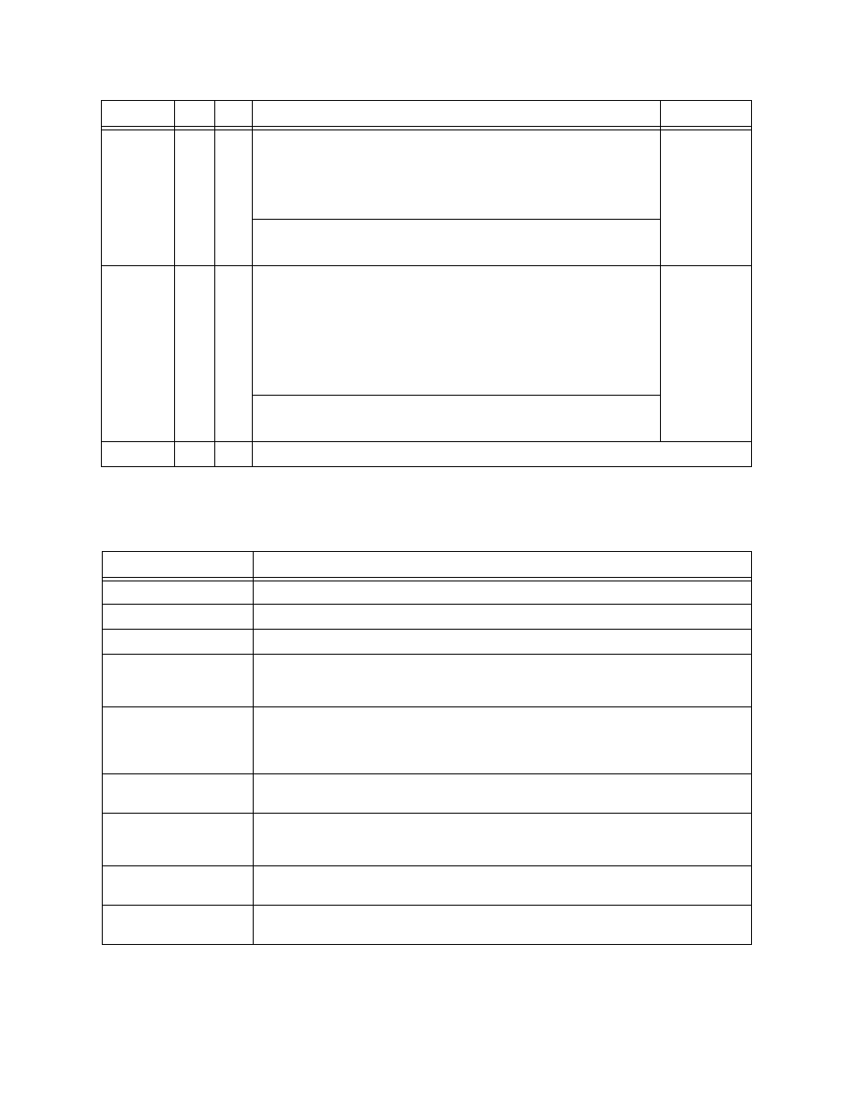
defines the status field (lower portion) of the IMUX
Configuration Menu.
Table 3-3 Status Field Definitions
RI
X
In V.35 Mode:
RI—RI stands for Ring Indicator. Ring Indicator is used on POTS
(Plain Old Telephone Service) switched network modems to
indicate that the telephone line is ringing from an incoming
telephone call.
In HSSI Mode:
RI displays “Yes”, but this has no meaning.
1) No
2) Yes
TM
X
In V.35 Mode:
TM—Test Mode. A lead defined in synchronous serial interface
protocols that the DCE can use to indicate to the DTE that the DCE
is in a test mode. In automatic DTE handshake mode, TM is “On”
during a test and “Off” when there is no test.
In manual DTE handshake mode TM is forced off at all times if
this field says “No”, or forced on at all times if this field says “Yes”.
In HSSI Mode:
TM has no meaning.
1) No
2) Yes
X
X
X
Exit this menu
Command V.35 HSSI
Description
Options
Status Field
Definition
FW Rev
Displays the current firmware revision for the active partition of this IMUX.
Line Type
Displays the type of line connected to the IMUX, only T1 at this time.
Channel Rate
Displays the data rate used by the IMUX for the T1 line.
Lines Equipped
This informational field indicates which ports the IMUX has been configured to
use in the Circuit Manager Menu. An "X" indicates a selected port, a blank
space indicates a port has not been selected.
Lines Active
Shows which lines are currently in use by this IMUX card. An “X” is displayed
when the IMUX card is using a T1 line. This indicates the associated network port
is in a frame sync condition and the IMUX card recognizes the framing pattern of
a remote IMUX.
Frame Sync
Shows that the selected IMUX card has recognized and synchronized with the
IMUX frame structure on the incoming (RX) signal on these lines.
CTS Received
Shows that the selected IMUX card has received (via IMUX frame signalling bits)
confirmation of frame detection and synchronization by the far-end IMUX card on
these lines.
CRC Error
Shows that a Cyclic Redundancy Check (CRC) error was detected in one or more
of a group of five (5) IMUX frames on these lines.
Far CRC Error
Shows that a Cyclic Redundancy Check (CRC) error was detected by the far-end
IMUX, in one or more of a group of five (5) IMUX frames on these lines.