Configuration switch s4 -3, Network framing -3, Alarm s5 s4 s6 s7 – Verilink PRISM 3001 (34-00186) Product Manual User Manual
Page 17
Unit Configuration
2-3
Therefore, when the unit is first received for installation or if power has not been
applied for an extended period of time, the configuration should be verified using
either the terminal interface, element manager, or site controller. The battery
becomes fully charged after power has been applied for 160 hours.
Hardware switches on the side of the circuit boards provide the means to configure
most simple applications. These configuration switches are described in the
following paragraphs. When power is applied to the unit, the front panel indicators
flash for approximately 10 seconds as the unit executes a self -test function. If an
ambiguous configuration has been programmed, the front panel indicators continue
to flash after the self-test is completed. The configuration must then be reviewed
to correct the error.
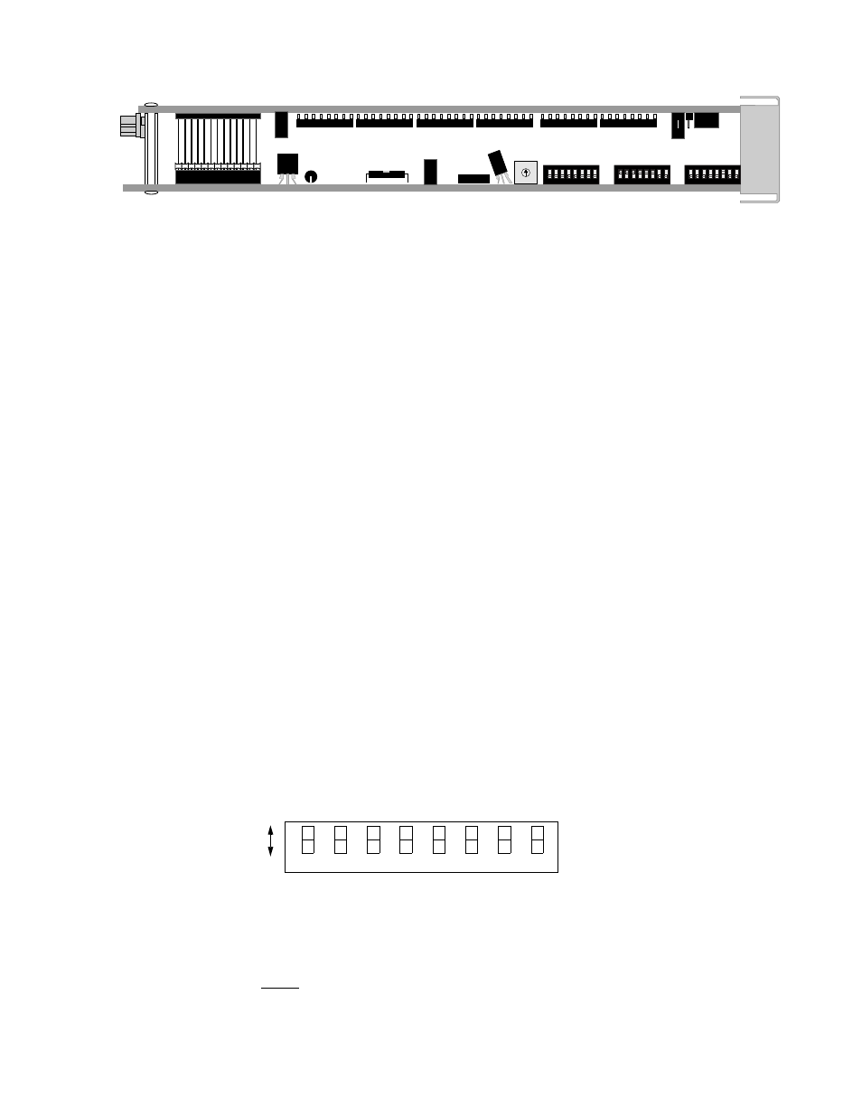
The unit is hardware configured using three DIP switches, a rotary switch, and two
jumpers. All are located on the top edge of the circuit boards (refer to Figure 2-1
above). The front panel rotary switch selects BERT patterns and is described in the
Operations chapter. The numbering system used for each switch position is as
follows: Position 2 of Switch S4 is referred to as Switch S4 -2, and so on.
Before installation, verify each configuration switch setting. A removable
configuration guide is included in the rear of this manual to record option
selections for reference.
Configuration
Switch S4
Switch S4 is used to set the configuration parameters listed in the following
paragraphs.
Network Framing
Position S4-1 is used to match the unit to the framing of the network line.
Down: ESF
Up: D4
0
1
2
3
4
5 6
7
9
8
1 2 3 4 5 6 7 8
1 2 3 4 5 6 7 8
1 2 3 4 5 6 7 8
Alarm
S5
S4
S6
S7
Figure 2-1 Top-edge View of PRISM 3001
7
6
5
4
3
2
1
Dn
Up
8
Network
Network
Network
Clo
c
k
Ch
an
n
el
Fra
m
in
g
C
o
di
ng
Assig
n
me
nt
So
urc
e
Clo
c
k
So
urc
e
LBO
Network
LBO
Bit
Rates
Figure 2-2 Switch S4