Chassis unit -14, Power connection -14, Stand-alone unit -14 – Verilink PRISM 3001 (34-00186) Product Manual User Manual
Page 28: Power connection, D/i option
2-14
I
NSTALLATION
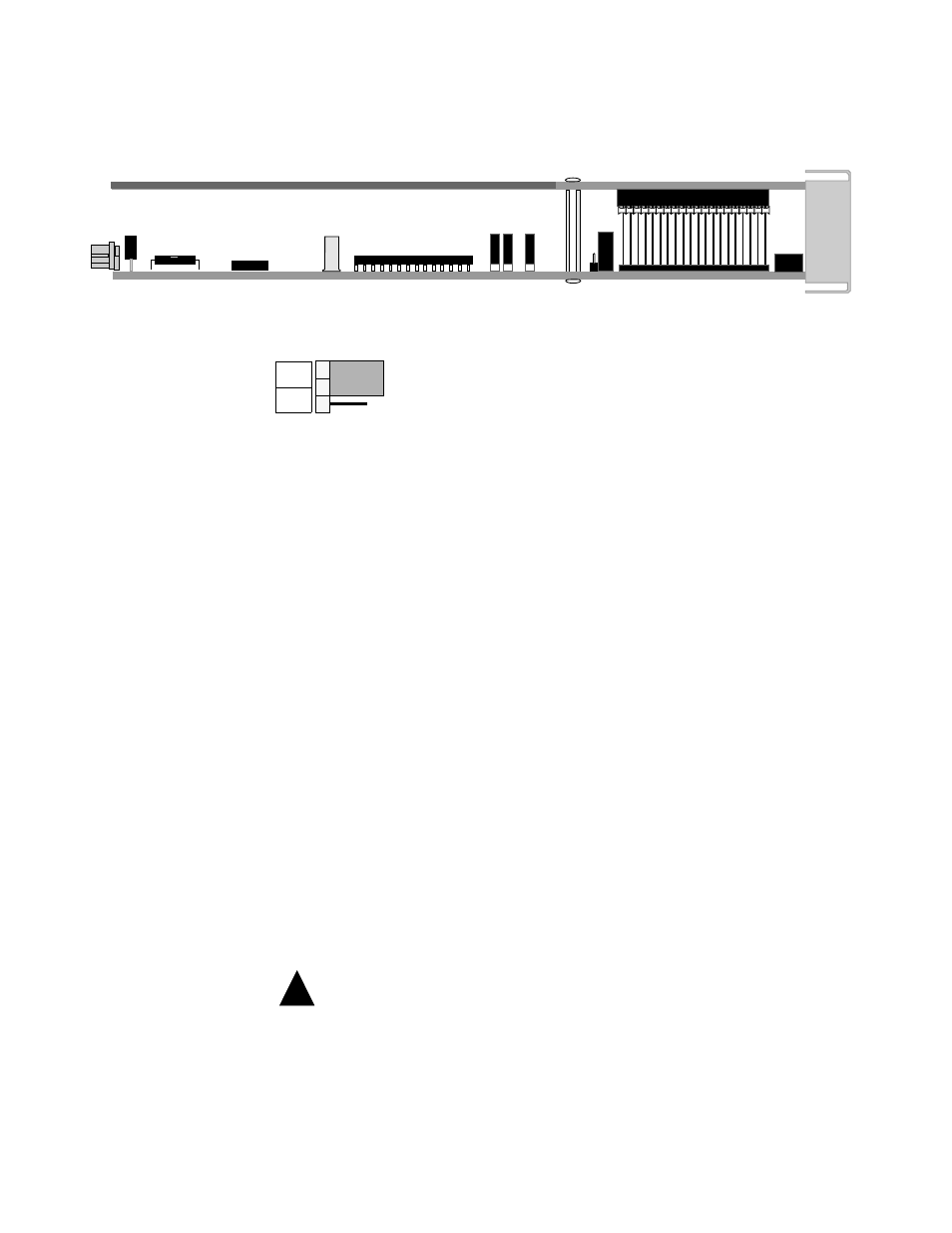
Pin 5 is configured to operate in either a normally open (NO) or normally closed
(NC) mode as determined by the setting of the alarm relay jumper shown below.
This jumper is located on the circuit board as shown in Figure 2-8.
NO and NC refer to the contact’s relationship to the common contact under a no
alarms condition. Move the jumper to NC for normally closed operation (opens on
alarm) or to NO for normally open operation (closes on alarm).
Make connections to the contacts using 20-gauge stranded wire (or similar).
Contacts are rated at 0.3 amperes AC or 1.0 amperes DC.
Chassis
Unit
Alarm conditions from all modules in the chassis are bused together in parallel and
are presented on a single set of alarm relay contacts which permit connection to a
remote indicating device. When connected, Pins 3 and 4 on terminal strip TB1
operate in a normally open mode. Refer to the 1051 -2 Chassis Configuration
Guide for more information.
All PRISM 3001 modules in a common chassis must use the normally open contact mode.
Make connections to the alarm contacts using 20-gauge stranded wire (or similar).
The contacts are rated at 120 mA AC or 120 mA DC.
Power
Connection
The stand -alone unit and the modular chassis unit require a -48 VDC power
source that is capable of supplying 165 mA current. Power supplies are available
from TxPORT and are listed in Table 1-2 on page 1-8.
Stand-alone
Unit
The power source is connected to pins 1 and 3 of the Power and Alarm terminal as
shown in Table 2-15.
Connect the ground lead before applying power to the unit.
Connect a chassis ground lead (18 - to 20 -gauge is recommended) to the Frame
Ground terminal (pin 4). Connect the other end of this lead to an appropriate
facility ground. Often, the 48 VDC return is also ground. In that case, both return
and ground leads should be connected to ground.
D/I Option
Figure 2-8 Bottom-edge View of the PRISM 3001
NC
NO
Figure 2-9 Alarm Relay Jumper
!