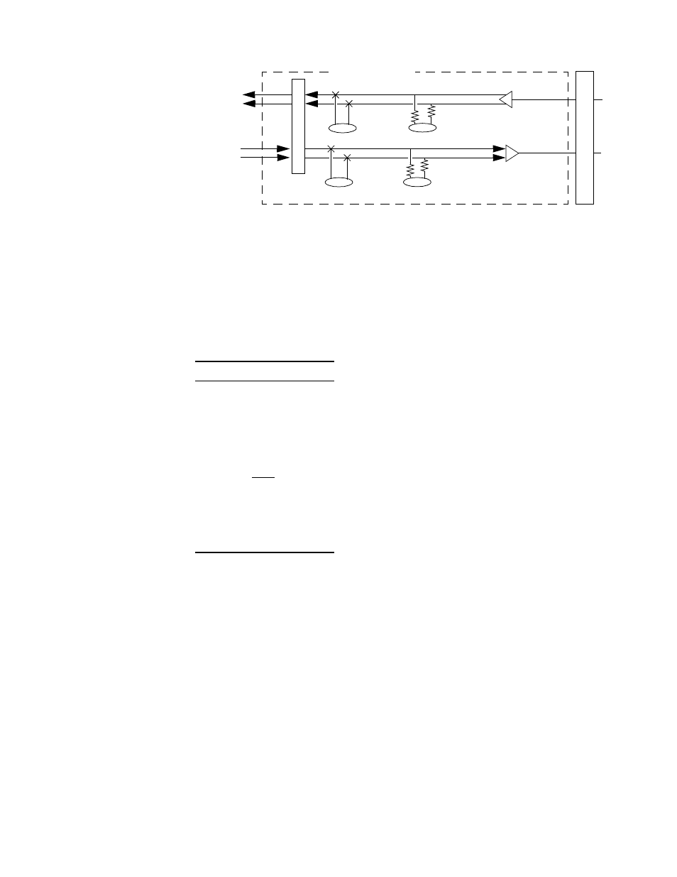
Bert pattern select -4 supervisory port -4, N figure 3-2 – Verilink PRISM 3001 (34-00186) Product Manual User Manual
Page 34
3-4
O
PERATION
BERT
Pattern
Select
This rotary switch determines the BERT pattern sent when the Test switch is in the
FAR position. Table 3-1 shows the corresponding BERT test pattern sent when the
rotary switch is set to positions 0 through 9. Additional patterns are available
through the Terminal Interface program (refer to Bit Error Rate Testing (BERT)
on page 4 -13).
When the switch is set to Flash (position 9) and the test switch is set to Local, the unit goes
into the Flash download mode automatically. If the unit is placed in this mode accidentally,
simply set the switch to another position and wait while the unit reboots.
Supervisory Port
This 6 -pin modular RS-232 supervisory jack provides direct terminal access for
controlling the unit and gathering status and performance data.
The supervisory port serves several functions. A terminal may be connected to this
port for external software control. A modem may be connected for remote access.
The port supports the call on alarm feature. The EM8000 Element Manager or
8100A Site Controller may be also connected through this port. Refer to
Supervisory Port Connection on page 2-9 for connection information.
Figure 3-2 Monitoring and Network Jacks in the PRISM 3001
P
ro
te
c
tio
n
Monitor
Insert
from
NET
Monitor
Network
Insert
to
NET
DTE Interface
CSU Ci
rc
ui
tr
y
Line Drivers
/Receivers
Table 3-1 BERT Patterns
Position
Pattern
0
QRSS
1
1 in 8
2
3 in 24
3
2047
4
2
20
-1
5
Clear
6
63
7
511
8
Factory use only
9
Flash