Wlan antenna – HP Spectre x2 User Manual
Page 45
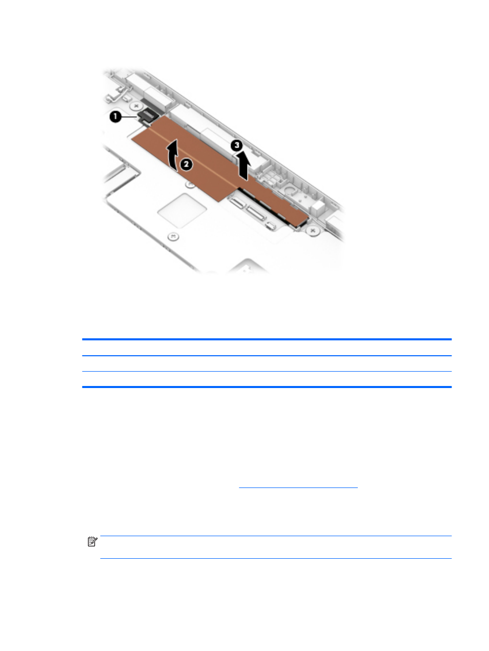
3.
Remove the 3D camera board (3) and cable.
4.
Remove the 3D camera board and cable.
Reverse this procedure to install the 3D camera board.
WLAN antenna
Description
Spare part number
WLAN auxiliary antenna (includes cable, auxiliary transceiver, and double-sided adhesive)
830329-001
WLAN main antenna (includes cable, main transceiver, and double-sided adhesive)
830330-001
Before removing the WLAN antenna, follow these steps:
1.
Turn off the slate. If you are unsure whether the slate is off or in Hibernation, turn the slate on, and then
shut it down through the operating system.
2.
Disconnect the power from the slate by unplugging the power cord from the slate.
3.
Disconnect all external devices from the slate.
4.
Remove the display panel assembly (see
Display panel assembly on page 20
).
Remove the WLAN antenna:
1.
Disconnect the WLAN antenna cables (1) from the terminals on the WLAN module built onto
the system board.
NOTE:
The WLAN “Main/#1”antenna cable is connected to the WLAN module “Main” terminal. The
WLAN “Aux/#2”antenna cable is connected to the WLAN module “Aux” terminal.
2.
Detach the WLAN antenna transceivers (2) from the back cover. (The WLAN antenna transceivers are
attached to the back cover with double-sided adhesive.)
Component replacement procedures
35