Wiring details, Technical guide mua ii controller 13 outside air, Temperature sensor – WattMaster MUA II User Manual
Page 13: Remote occupied contact
Technical Guide
MUA II Controller
13
Outside Air
Temperature Sensor
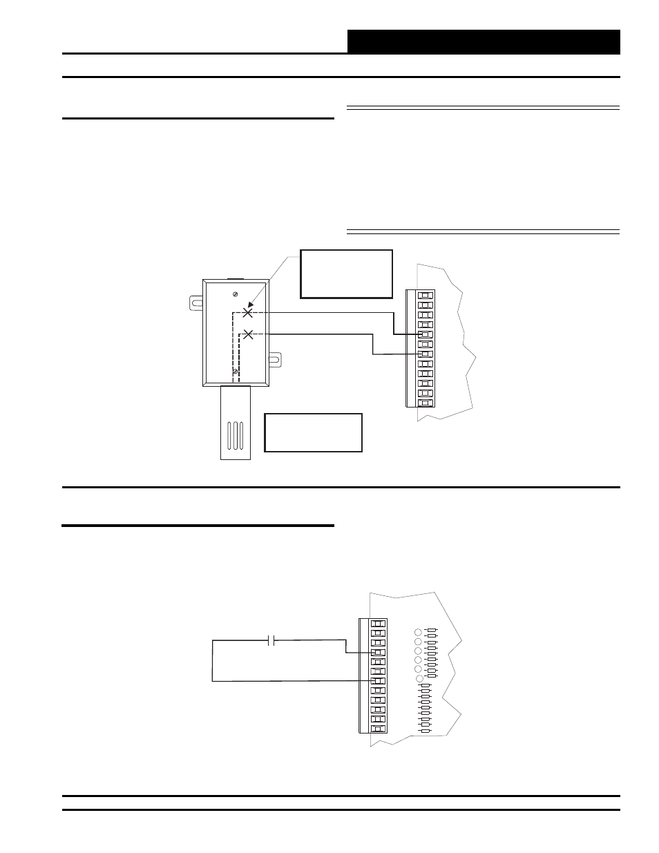
The Outside Air Sensor must be wired as shown in the illustration
below for proper operation. The Outside Air Temperature Sensor is a
10K Type III thermistor sensor. The sensor should be mounted in the
upright position as shown in an area that is protected from the elements
and direct sunlight. Be sure to make the wiring splices inside of the
Outside Air Temperature Sensor weathertight enclosure. See Figure
10 for detailed wiring.
Caution:
Be sure to mount the Outside Air Sensor in
an area that is not exposed to direct sunlight. A
shaded area under the eve of the building or
under the HVAC unit rainhood is normally a
good location. If the sensor is not located as
specifi ed, erroneous outside air temperature
readings will result. Unused conduit opening(s)
must have closure plugs installed and must be
coated with sealing compound to provide rain
tight seal. Water can damage sensor!
GND
INPUTS
GND
AOUT1
AOUT2
GND
+VDC
AIN1
AIN2
AIN3
AIN4
AIN5
AIN7
Outdoor
Air Temperature
Sensor
Make Splice Connections
Inside Sensor Enclosure
As Shown. Seal All
Conduit Fittings With
Silicone Sealant.
Mount Sensor Outdoors
In Shaded Protected
Area & In Upright
Position As Shown
Figure 10: Outside Air Temperature Sensor Wiring
GND
INPUTS
GND
AOUT1
AOUT2
GND
+VDC
AIN1
AIN2
AIN3
AIN4
AIN5
AIN7
MUA II Controller Board
Remote Occupied
Contact
(Relay By Others)
Figure 11: Remote Occupied Contact Wiring
Remote Occupied Contact
A Remote Occupied contact closure supplied from another Building
Automation System device can be used to enable Occupied and Unoc-
cupied modes on the MUA II Controller. This relay contact must be
a dry contact and be wired as shown below. See Figure 11 below for
detailed wiring.
Wiring Details