Wiring details, Technical guide mua ii controller 15, Space humidity sensor – WattMaster MUA II User Manual
Page 15: Fan proof of flow switch, Figure 13: space humidity sensor wiring, Figure 14: fan proof of flow switch wiring
Technical Guide
MUA II Controller
15
GND
INPUTS
GND
AOUT1
AOUT2
GND
+VDC
AIN1
AIN2
AIN3
AIN4
AIN5
AIN7
MUA II Controller Board
250 Ohm
Resistor
(Shipped With Sensor)
To be Installed Between
AIN7 and GND
The Pull-up Resistor (PU7)
Must Be Removed
When Using A 4-20ma Device
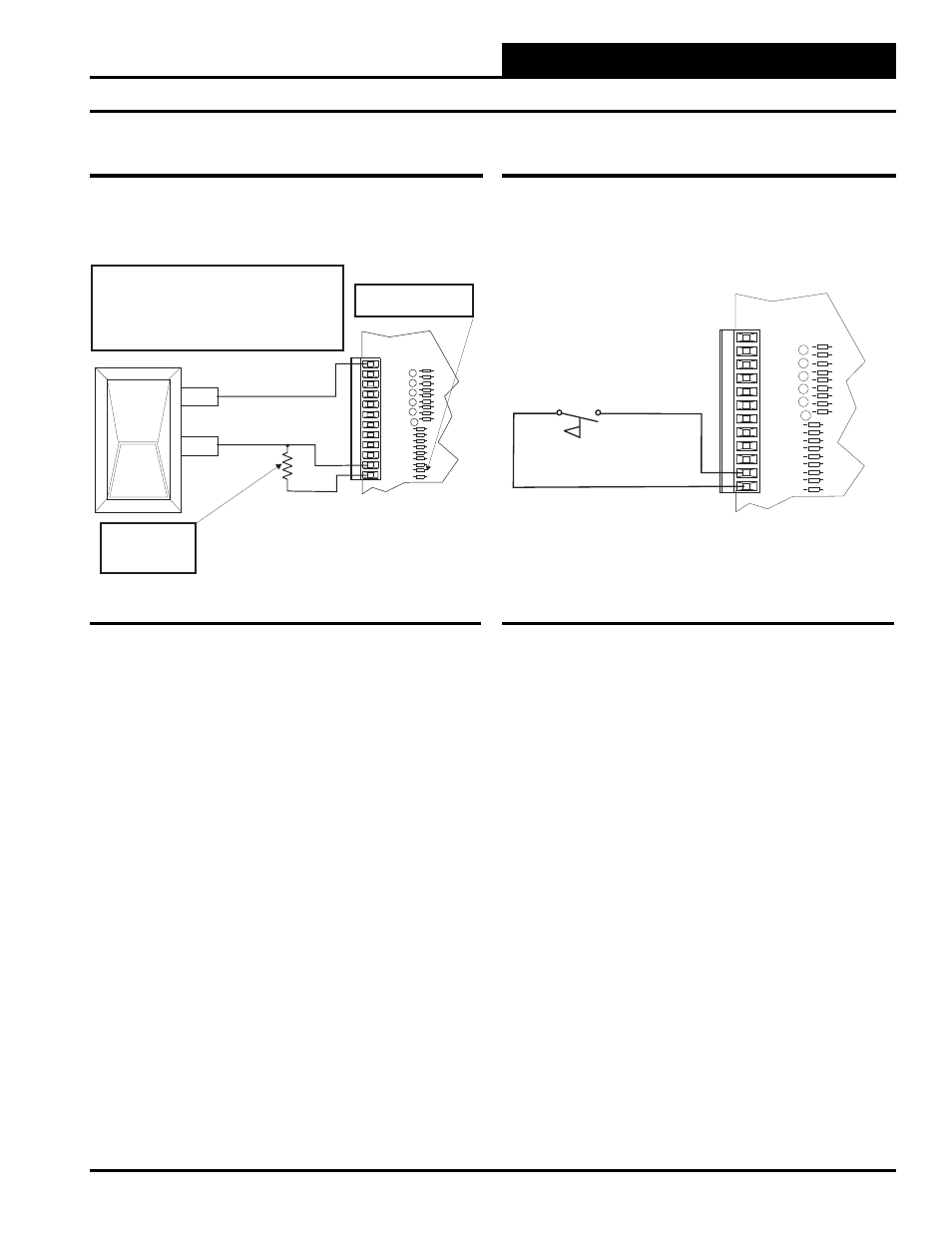
If You Are Using The Standard Factory Supplied Humidity Sensor, It Has
Terminals Labeled “+ (T1)” And - (T2)”. Terminal + (T1)” Is The Voltage
Input And Should Be Connected To The Terminal Labeled +VDC On The
MUA II Controller. Terminal “- (T2)” Is The 4-20 Ma Output Signal And
Should Be Connected To The Terminal Labeled AIN7 On The MUA II
Controller.
If A
Sensor Other Than The One Supplied By The Factory Is Used, Refer To
The Wiring Instructions Shipped With The Sensor.
A Factory Supplied 250 Ohm Resistor Should Be Connected
Between AIN 7 And A Ground Terminal On The MUA II Controller.
+ (T1)
- (T2)
Figure 13: Space Humidity Sensor Wiring
Space Humidity Sensor
A Space Humidity Sensor or a Fan Proof of Flow Switch can be con-
nected to AIN7 on the MUA II Controller. Shown below is the Space
Humidity Sensor wiring.
Fan Proof of Flow Switch
If a Fan Proof of Flow Switch is required, then obviously the Space
Humidity Sensor option is not available. By the same token, if a Space
Humidity Sensor is required, then the Fan Proof of Flow Switch option
is not available. See Fan Proof of Flow Switch wiring below.
GND
INPUTS
GND
AOUT1
AOUT2
GND
+VDC
AIN1
AIN2
AIN3
AIN4
AIN5
AIN7
MUA II Controller Board
Fan Proof Of Flow
Switch
Figure 14: Fan Proof of Flow Switch Wiring
Wiring Details