Start-up & commissioning, Technical guide mua ii controller 17, Initialization – WattMaster MUA II User Manual
Page 17: Programming the controller
Technical Guide
MUA II Controller
17
Check all wiring leads at the terminal block for tightness. Be sure that
wire strands do not stick out and touch adjacent terminals. Confi rm that
all sensors required for your system are mounted in the appropriate loca-
tion and wired into the correct terminals on the MUA II Controller. Be
sure any expansion boards connected to the MUA II Controller are also
correctly wired just as you did for the MUA II Controller.
After all the above wiring checks are complete, apply power to the MUA
II Controller and all expansion boards connected to it.
Initialization
Upon applying power to the MUA II Controller, the following should
occur:
On system power-up, a 30 second start-up delay is performed where
all default setpoints are initialized, LEDs are initialized, and all outputs
are turned off.
When power is fi rst applied, LED2 is turned off for 5 seconds. At this
time, the LED will “blink” to indicate the setting of the address switch
and then extinguish for another 5 seconds. The LED will now “blink”
for a 30-second start-up delay to protect the fan and other components
from short cycling during intermittent power conditions. If all inputs are
operating correctly, the LED will blink once every ten seconds.
The PWR LED should glow continuously. If this is a stand-alone or
interconnected system, the COMM LED should also glow continuously
after its initial start-up routine. If this is a networked system, the COMM
LED should fl icker approximately once every second to indicate commu-
nications are occurring. If the LEDs are behaving as indicated, proceed
to the next step. If the LEDs fail to light or do not behave as indicated,
please proceed to the troubleshooting section of this manual to diagnose
and correct the problem before proceeding with the start-up process.
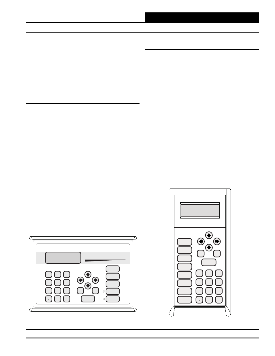
Programming The Controller
The next step is programming the controller for your specifi c require-
ments. In order to confi gure and program the MUA II Controller, you
must have a central Operator’s Interface or a personal computer with
the Prism computer front-end software installed. Two different central
operator’s interfaces are available for programming of the MUA II Con-
troller. You may use either the Modular Service Tool or the Modular
System Manager to access the status and setpoints of any controller on
your communications loop. See the Modular Service Tool and System
Manager Programming Guide for MUA II Controller programming.
If you are going to use a personal computer and the Prism computer
front-end software, please see the Prism Graphical Communications
Interface Technical Guide. No matter which operator’s interface you
use, it is recommended that you proceed with the programming and
setup of the controller in the order that follows:
1. Confi gure the controller for your application.
2. Program the controller’s setpoints.
3. Program the controller’s operation schedules.
4. Set the controller’s current time and date.
5. Review controller status screens to verify system
operation and correct controller confi guration.
Start-up & Commissioning
Mode
Selection
ENTER
CLEAR
ESC
PREV
NEXT
DOWN
UP
6
5
4
DEC
7
0
8
1
3
2
9
MINUS
-
STATUS
SETPOINTS
SCHEDULES
CONFIGURATION
ALARMS
ON
OVERRIDES
BALANCE - TEST
Figure 16: Operator’s Interfaces
ENTER
CLEAR
ESC
PREV
NEXT
DOWN
UP
6
5
4
DEC
7
0
8
1
3
2
9
MINUS
-
STATUS
SETPOINTS
SCHEDULES
ALARMS
OVERRIDES
System Manager