Appendix – WattMaster MUA II User Manual
Page 27
Technical Guide
MUA II Controller
27
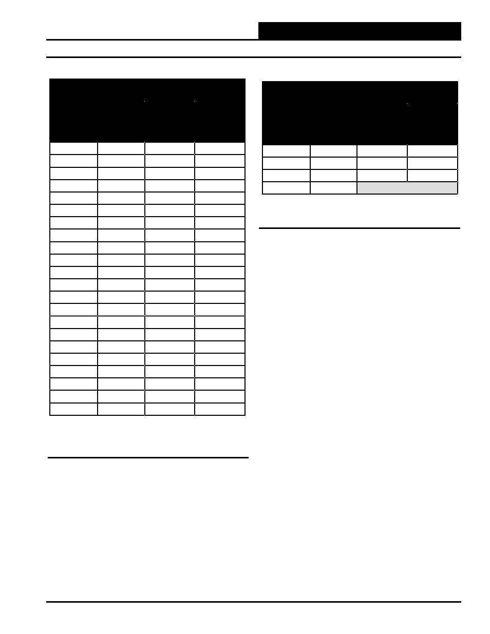
OE265 Relative Humidity Sensors
Testing Instructions:
Use the voltage column to check the Humidity Sensor while connected
to a powered controller.
Read the voltage with meter set on DC volts. Place the “-” (minus) lead
on GND terminal and the “+”(plus) lead on the sensor input terminal
being investigated.
If the voltage is above 5.08 VDC, then the sensor or wiring is “open.” If
the voltage is less than 0.05 VDC, the sensor or wiring is shorted.
OE265-11, -13 & -14 Relative Humidity Transmitters –
Humidity vs. Voltage for 0-5 VDC Sensors
Humidity
Percentage
(RH)
Voltage
@
Input
(VDC)
Humidity
Percentage
(RH)
Voltage
@
Input
(VDC)
0%
0.00
44%
2.20
2%
0.10
46%
2.30
4%
0.20
48%
2.40
6%
0.30
50%
2.50
8%
0.40
52%
2.60
10%
0.50
54%
2.70
12%
0.60
56%
2.80
14%
0.70
58%
2.90
16%
0.80
60%
3.00
18%
0.90
62%
3.10
20%
1.00
64%
3.20
22%
1.10
66%
3.30
24%
1.20
68%
3.40
26%
1.30
70%
3.50
28%
1.40
72%
3.60
30%
1.50
74%
3.70
32%
1.60
76%
3.80
34%
1.70
78%
3.90
36%
1.80
80%
4.00
38%
1.90
82%
4.10
40%
2.00
84%
4.20
42%
2.10
86%
4.30
Table 4: Humidity/Voltage for OE265-11, -13 & -14
Humidity Sensors
OE265-11, -13 & -14 Relative Humidity Transmitters –
Humidity vs. Voltage for 0-5 VDC Sensors
Humidity
Percentage
(RH)
Voltage
@
Input
(VDC)
Humidity
Percentage
(RH)
Voltage
@
Input
(VDC)
88%
4.40
96%
4.80
90%
4.50
98%
4.90
92%
4.60
100%
5.00
94%
4.70
Table 4: Humidity/Voltage for OE265-11, -13 & -14
Humidity Sensors
Appendix