Northfire 42, 32 servicing – Archgard 42-DVT40N User Manual
Page 32
Northfire 42
32
SERVICING
•
Open the lower grills.
•
The pressure test taps are located on the valve.
Automatic valve:
The taps are located in the front. The supply pressure is marked ‘IN’ and
the manifold pressure is marked ‘OUT’. There is also an arrow marking the
direction of gas flow.
Manual valve:
The taps are located on the left side of the valve. The connection closest to
the back, marked with ‘IN’ is the supply pressure and the manifold pressure
marked with ‘OUT’ is closest to the front.
•
Loosen the set screw inside the tap with a ⅛” wide flat screw driver.
•
Connect a ¼” rubber tube to the tap and to the manometer.
•
Be sure to tighten the set screw inside the tap after you are finish taking pressure readings.
•
Check for leaks.
CHECKING SUPPLY AND MANIFOLD GAS PRESSURE
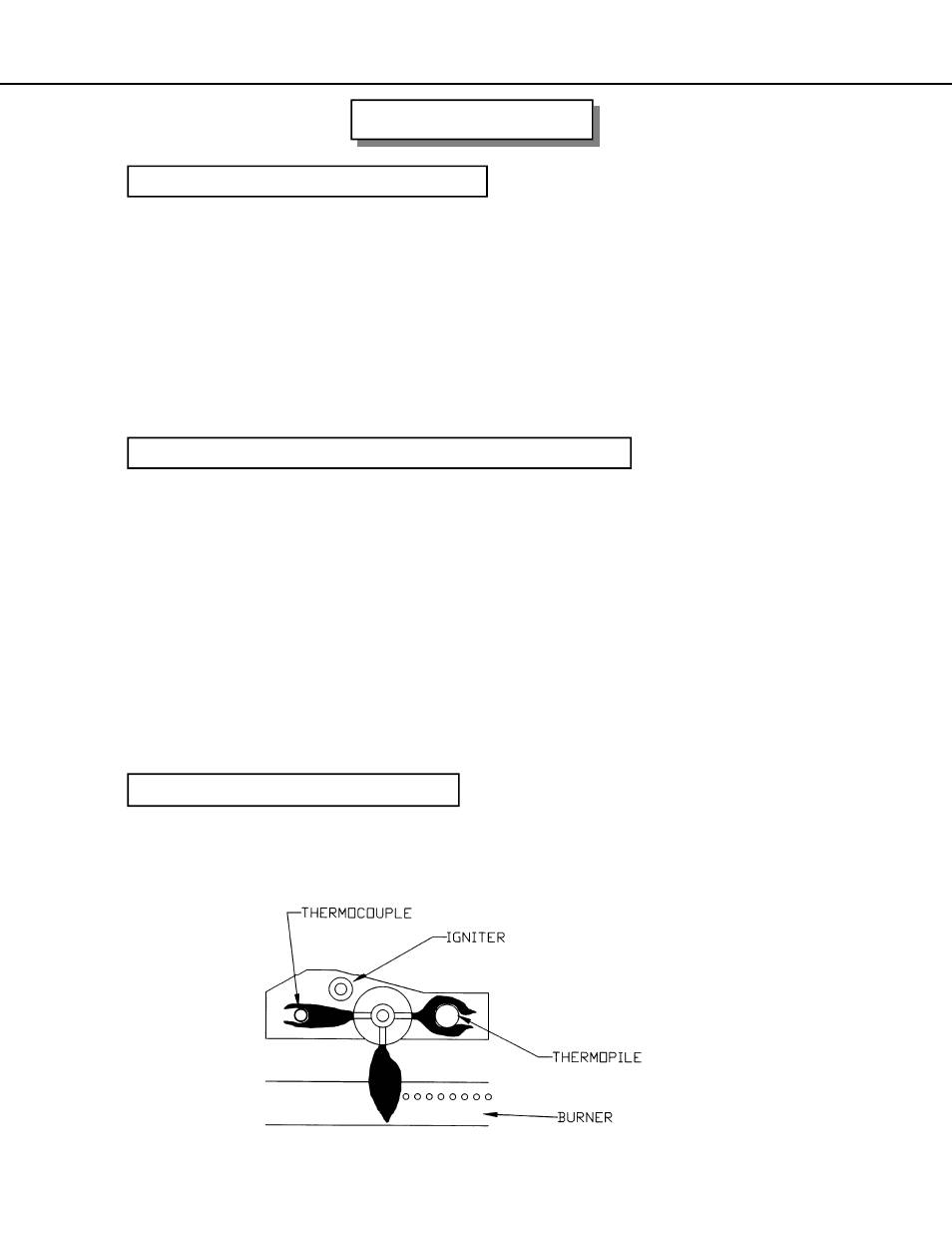
CHECKING AND ADJUSTING PILOT
The pilot flame should have the characteristic as shown in the illustration below. The flame
should not have yellow tips but should engulf the thermocouple and thermopile. It can be ad-
justed by turning the screw marked “pilot” on the control valve.
•
Remove the glass door, log branches and the front log.
•
Unscrew the 2 screws holding the left burner shields between the burner tubes and remove
the shield.
•
Remove the adjustment wing nut and slide the air shutter away from the orifice cap.
•
Use a ½” wrench to remove the orifice cap.
•
Change the orifice cap. Use a small quantity of gas thread seal compound. Do not over
tighten.
•
Replace the adjustment wing nut and properly set the primary air shutter according to the
specifications.
•
Replace the burner shield, front log, branches and the glass door.
CHANGING MAIN BURNER ORIFICE