Dvie33 – Archgard 31-DVIE33N User Manual
Page 16
31-DVIE33
16
VENTING INSTRUCTIONS
WARNING: Operation of this heater when not connected to a properly installed and maintained venting
system can result in carbon monoxide (CO) poisoning and possible death. The appliance must not be
connected to a chimney flue serving a separate solid fuel burning appliance.
The 31-DVIE33C
requires (2) flexible flue liners
:
INLET Collar - 3” (76 mm) diameter
OUTLET Collar - 3” (76 mm) diameter
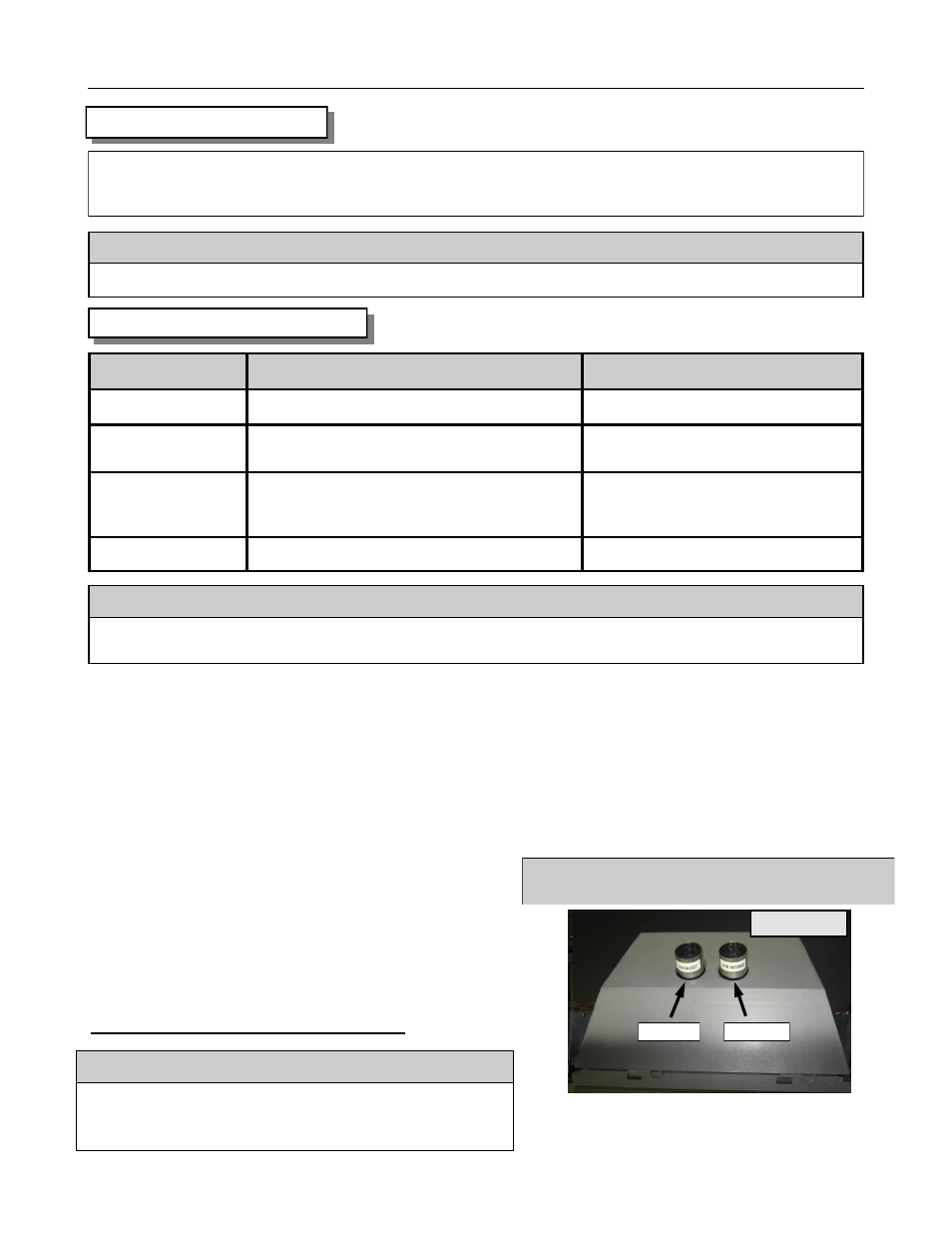
The 31-DVIE33C showing the Fresh Air Intake and
Exhaust locations. These connections are labeled.
The Air intake and Exhaust connections are marked on
the gas appliance. See picture.
DO NOT REVERSE THESE CONNECTIONS
Manufacturer Vertical Termination
Termination Adapter
Archgard
999-INS-TK
N/A
Dura Vent
980 - Co-Axial Cap (requires adapter)
991 - Co-Axial High Wind (requires adapter)
923GK (Co-Axial to Co-Linear)
ICC/Excel
IVT - Co-Linear
VT - Co-Axial (requires adapter)
SVT- Co-Axial (requires adapter)
N/A
CTA or CAA (Co-Axial to Co-Linear)
CTA or CAA (Co-Axial to Co-Linear)
Ameri-vent
DVC - Co-Axial Cap (requires adapter)
DCAT (Co-Axial to Co-Linear)
APPROVED TERMINATIONS
C A U T I O N
Only 3” (76mm) double wall aluminum flex liner and approved vent terminals are to be used for this appliance.
A T T E N T I O N
NO OTHER VENTING SYSTEM OR COMPONENTS MAY BE USED. Follow manufacturer instructions for
installation of termination.
This appliance is designed for dual 3” (76 mm) double wall aluminum flex liner, running the entire length of the
chimney.
The flue length must be a minimum of 10’ (3.05 M) and a maximum of 40’ (12.2 M)
The exhaust vent restrictor provided with this appliance must only be used by installing it onto the
front of the baffle when the vent height is over 18’ (5.5 M) if required.
The minimum (chimney) flue size is 4” x 7” (102 mm X 178 mm).
Masonry chimneys may take various contours which the flexible liner will accommodate, however, keep the
flexible liner as straight as possible, avoiding unnecessary bending but at all times keep a minimum of 3” (76
mm) inside bend radius.
The Air Intake Flex Liner must be connected to the inlet air
collars of the termination cap and the appliance.
The Exhaust Flex Liner must be connected to the exhaust
collars of the termination cap and the appliance.
Exhaust
Fresh Air
TOP VIEW
C A U T I O N
To ensure that the venting is not accidentally obstructed or punctured,
the damper of the host fireplace must be permanently disabled.
Either complete removal of the damper, or welding it in its “open” posi-
tion. Temporarily disabling the damper is not permissable.