Connecting the encoders – HEIDENHAIN PT 855 for Turning User Manual
Page 58
II - 1
Installation and Electrical Connection
60
Technical Information
POSITIP 855
Grounding
X4
Connecting the encoders
POSITIP can be used with HEIDENHAIN linear encoders that pro-
vide sinusoidal output signals. The encoder inputs on the rear panel
are designated X1, X2, X3 and X4.
The connecting cable length may not exceed 30 m (100 ft).
Danger to internal components!
Do not engage or disengage any connections while
the unit is under power.
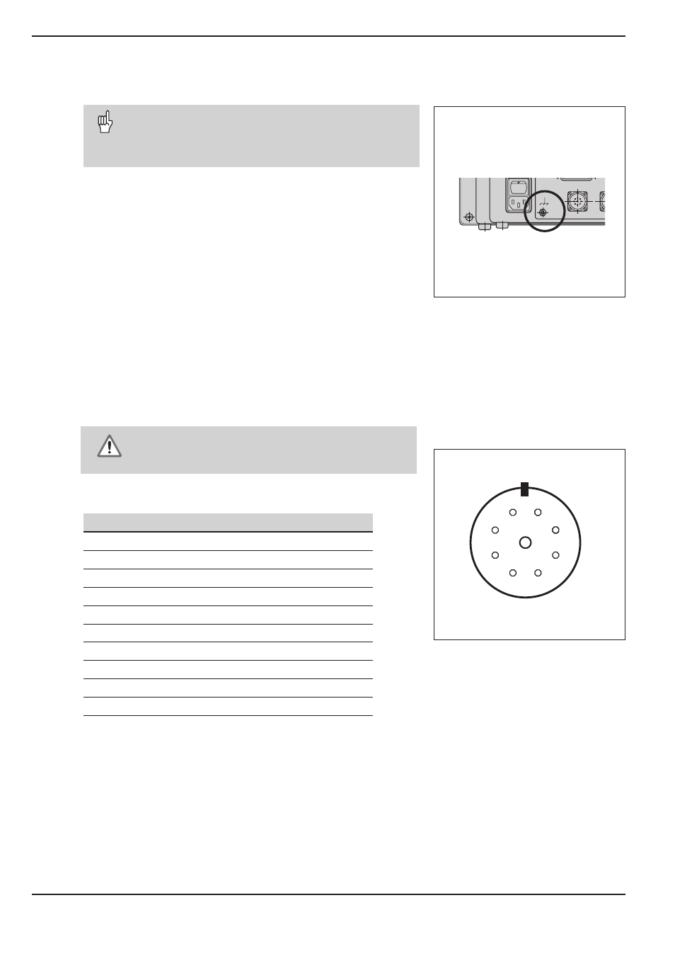
Pin layout for encoder inputs
Pin
Assignment
1
0°+
2
0°–
3
+5 V (U
P
)
4
0 V (U
N
)
5
90°+
6
90°–
7
Reference mark signal RI+
8
Reference mark signal RI–
9
Internal shield
Housing
External shield
2
3
4
5
7
1
9
6
8
Fig. 31: The ground screw on the rear panel
Noise immunity can be increased by connecting the
ground screw on the rear panel to the central ground
of the machine. Minimum cross-section of the
connecting wire: 6 mm
2
.
Fig. 32: Flange socket on POSITIP for encoder
signal input