2 powerline connection – SMA SB 4200TL HC Multi-String User Manual
Page 56
The Communications Interface
SMA
Technologie AG
Page 56
SBTLHCMS-IEN080411
Installation Guide
12. 2 Powerline Connection
This chapter describes the installation of the "Powerline Kit" (SMA order number:
NLMPB-MS-NR) for the mains grid communication in a Sunny Boy.
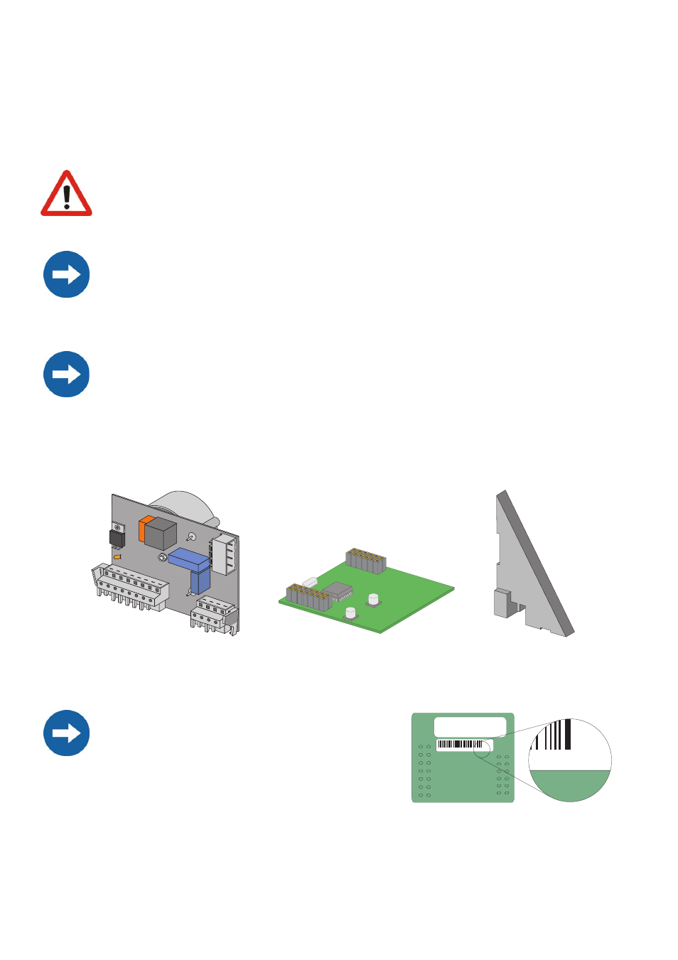
Two component groups must be installed in the Sunny Boy in order to make the mains
grid communication possible. These component groups and a support for the power
module are included in the "Powerline Kit" (SMA order number: NLMPB-MS-NR):
When opening the Sunny Boy, follow all the safety instructions as de-
scribed in section 3.
Electrostatic discharges are an acute danger to the Sunny Boy and to the commu-
nications interface. Ground yourself by touching PE before removing the commu-
nications interface from the packaging, and before touching any components
within the Sunny Boy.
Read the communication device manual before beginning installation work. Fur-
ther wiring details can be found there.
The Sunny Boy can only be operated with a
powerline modem (NLM Piggy-Back) with ver-
sion identifier "F" or higher. When installing the
other (older) Piggy-Backs, mains grid connec-
tion is not possible. Please use therefore the
powerline modem (NLM Piggy-Back) which is
included in the "Powerline Kit".
PLC power module
Powerline modem
(NLM Piggy-Back)
Support for the
PLC power module
339363 26584
F
F
MOSR05-NLM