Electronic lineshaft with alignment, 2 example configuration diagram, 2 example wiring diagram – Yaskawa G5 Electronic Lineshaft Alignment User Manual
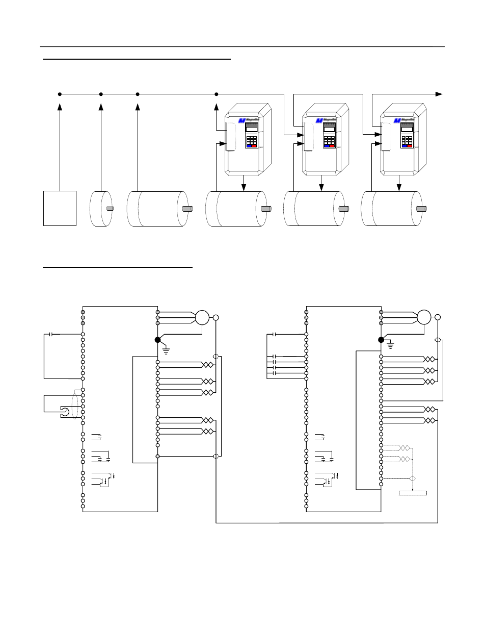
Page 4: Master drive, Slave drive, Pg-x2 pcb option, Gpd515, Pg-w2 pcb option
Electronic Lineshaft with Alignment
Date: 07-01-04, Rev: 04-07
Page 4 of 15
TM.G5SW.046
1.2 Example Configuration Diagram
1.2 Example Wiring Diagram
PG
-X
2
GPD
515
PG
-W
2
GPD
515
E
n
coder
Master
Motor
E
n
coder
Slave 1
Motor
PG
-W
2
GPD
515
E
n
coder
Slave 2
Motor
G114712
Software
G114712
Software
Any Software
Master Source Signal
to the 1
st
Slave GPD515 Drive
Master Source Signal
to the 3
rd
Slave GPD515 Drive
E
n
coder
Motor
E
n
coder
Pulse
Generator
+A Pulse
-A Pulse
+B Pulse
-B Pulse
OR
OR
Master Source Signal
to the 2
nd
Slave GPD515 Drive
OR
OR
M
ast
er Source O
p
ti
on 1
M
ast
er Source O
p
ti
on 2
M
ast
er Source O
p
ti
on 3
M
ast
er Source O
p
ti
on 4
Gray -A
IM
Red 5-15VDC
Black Common
Blue +A
Gray -A
Green +B
Yellow -B
1
2
3
4
5
6
7
8
9
MGL
PG-X2 PCB Option
enc
oder
T1
T2
T3
GPD515
L1
L2
L3
1 FWD Run
2 REV Run
3 EXT Fault
4 Fault Reset
5 Definable
6 Definable
7 Definable
8 Definable
11 Common
12 GND
13 Input 0-10V
14 Input 4-20mA
15 Supply +15V@20mA
16 Input 0-10V
17 Supply Common
TA2
T
A1
Motor
Master Drive
1
2
3
4
5
6
Blue +A
Green +B
Yellow -B
9
10
18
19
20
33 Supply -15V@20mA
25
26
27
23 Analog Output +/- 10 VDC
24 Analog Output +/- 10 VDC
25 Analog Output Common
Shield
IM
Red 5-15VDC
Black Common
Blue +A
Gray -A
Green +B
Yellow -B
1
2
3
4
5
6
7
8
9
MGL
PG-W2 PCB Option
enc
oder
T1
T2
T3
GPD515
G11471x
L1
L2
L3
1 FWD Run
2 REV Run
3 EXT Fault
4 Fault Reset
5 DisableLineshaft
6 Slave Trigger
7 Master Trigger
8 Align Slave
11 Common
12 GND
13 Input 0-10V
14 Input 4-20mA
15 Supply +15V@20mA
16 Input 0-10V
17 Supply Common
Motor
Slave Drive
11
12
13
14
15
16
Blue +A
Gray -A
Green +B
Yellow -B
9
10
18
19
20
33 Supply -15V@20mA
25
26
27
23 Analog Output +/- 10 VDC
24 Analog Output +/- 10 VDC
25 Analog Output Common
10
17
18
19
20
21
22
23
24
TA3
+A
-A
+B
-B
To Next Drive
Shield
Disable
S Align Switch
M Align Switch
Alignment Sw
Enable / Run
Run
Speed Ref