Yaskawa J7 to J1000 User Manual
Page 16
(Header Title) Application Note
Doc#: PL.J1000.01 Copyright Yaskawa Electric America, Inc.©2008 www.yaskawa.com August 1, 2008 16 of 19
Subject: Transition Guide
Product: J1000
Document: PL.J1000.01
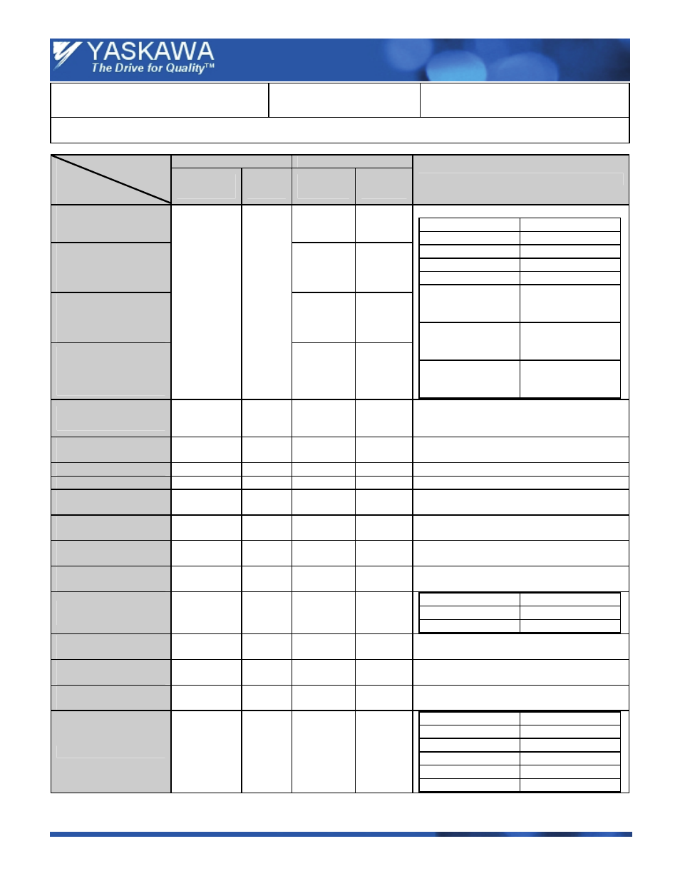
Title: Product Transition Guide – J7 to J1000
Product Transition Guide – J7 to J1000
J7
J1000
Drive
Function
/ Parameter
Parameter
No.
Initial
Value
Parameter
No.
Initial
Value
Comments
Carrier Frequency
Selection
C6-02
o2-04
dep.
Carrier Frequency
Upper Limit
C6-03
C6-02
dep.
Carrier Frequency
Lower Limit
C6-04
C6-02
dep.
Carrier Frequency
Proportional Gain
n46
4
Depends
on drive
capacity.
C6-05 0
J7 J1000
n46 Æ 1
C6-02 Æ 1 (2 kHz)
n46 Æ 2
C6-02 Æ 2 (5 kHz)
n46 Æ 3
C6-02 Æ 3 (8 kHz)
n46 Æ 4
C6-02 Æ 4(10 kHz)
n46 Æ 7
C6-03 = 2.5
C6-04 = 1.0
C6-05 = 12
n46 Æ 8
C6-03 = 2.5
C6-04 = 1.0
C6-05 = 24
n46 Æ 9
C6-03 = 2.5
C6-04 = 1.0
C6-05 = 36
Momentary Power Loss
Detection Selection
n47
0 L2-01 0
—
Automatic Fault Reset
Attempts
n48 0
L5-01 0
—
Jump Frequency 1
n49
0.0 Hz
d3-01
0.0 Hz
—
Jump Frequency 2
n50
0.0 Hz
d3-02
0.0 Hz
—
Jump Frequency
Bandwidth
n51
0.0 Hz
d3-04
1.0 Hz
—
DC Injection Braking
Current
n52 50%
b2-02 50%
—
DC Injection Time at
Stop
n53
0.0 s
b2-04
0.50 s
—
DC Injection Time at
Start
n54
0.0 s
b2-03
0.00 s
—
Stall Prevention During
Deceleration
n55 0
L3-04 1
J7 J1000
n55 Æ 0
L3-04 Æ 1
n55 Æ 1
L3-04 Æ 0
Stall Prevention During
Acceleration
n56 170%
L3-02 —
Initial value of J1000 depends on Duty Mode
Selection (C6-01).
Stall Prevention Level
During Run
n57 160%
L3-06 —
Initial value of J1000 depends on Duty Mode
Selection (C6-01).
Output Frequency
Detection Level (DO)
n58
0.00 Hz
L4-01
0.0 Hz
—
Over Torque Detection
n59 0
L6-01 0
J7 J1000
n59 Æ 0
L6-01 Æ 0
n59 Æ 1
L6-01 Æ 1
n59 Æ 2
L6-01 Æ 2
n59 Æ 3
L6-01 Æ 3
n59 Æ 4
L6-01 Æ 4