Yaskawa J7 to J1000 User Manual
Page 6
(Header Title) Application Note
Doc#: PL.J1000.01 Copyright Yaskawa Electric America, Inc.©2008 www.yaskawa.com August 1, 2008 6 of 19
Subject: Transition Guide
Product: J1000
Document: PL.J1000.01
Title: Product Transition Guide – J7 to J1000
Product Transition Guide – J7 to J1000
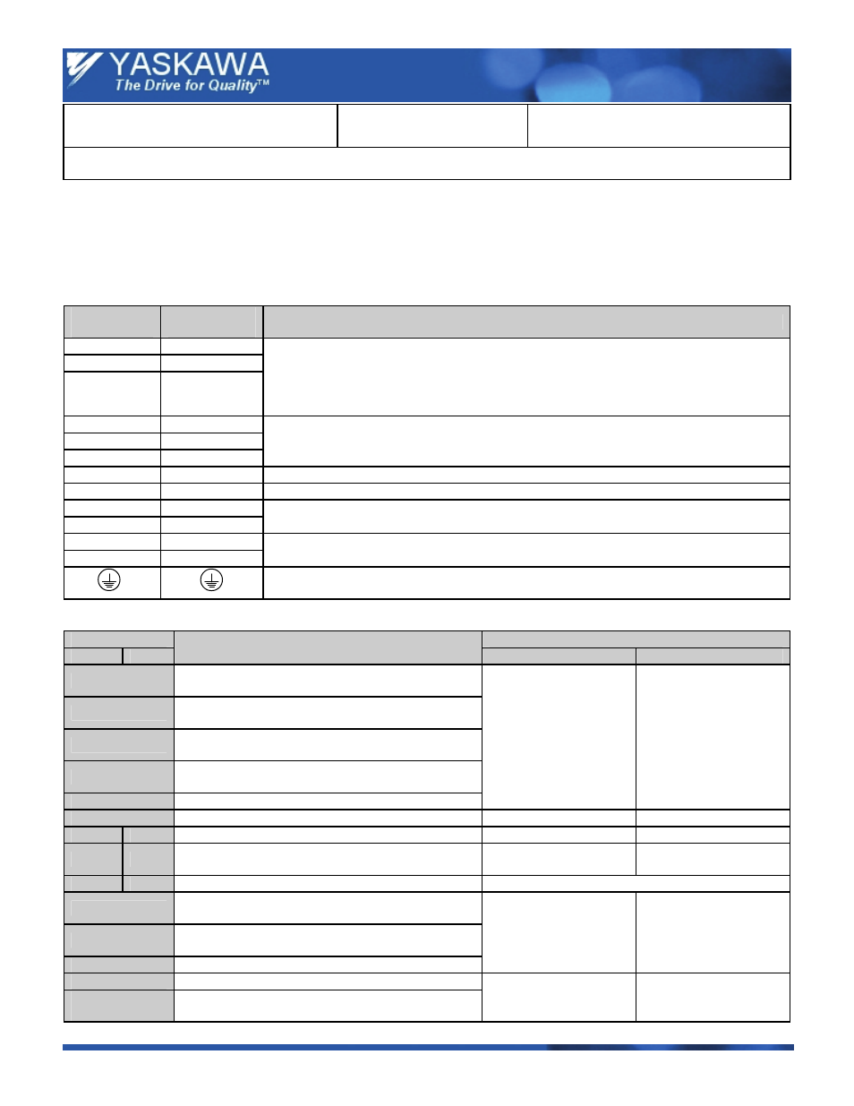
4.0 Terminals
4.1 Main Circuit Terminals
Note:
The J7 and J1000 drives may have different terminal sizes (depending on capacity); therefore, the terminals must be
carefully checked before replacement. The main terminal functionality has not been changed.
J7 Main
Terminals
J1000 Main
Terminals
Note
R / L 1
R / L 1
S / L2
S / L2
T / L 3
T / L 3
Power supply connection.
Note:
In the J7 drive the power supply terminals are located at the top of the drive. In the J1000
the power supply terminals are located at the bottom of the drive. Cables must fit without
tension (replace or extend if needed).
U / T1
U / T1
V / T2
V / T2
W / T3
W / T3
Drive Output
-
B1
Braking resistor or external braking chopper connection.
-
B2
Braking resistor connection.
+1 +1
+2 +2
DC Link Choke connection, DC Power Supply input.
+1 +1
— —
DC Power Supply input, external braking transistor module connection.
Grounding Terminal: For 200 V class: 100 Ω or less
For 400 V class: 10 Ω or less
4.2 Control Terminals, Signal Levels
Terminal
Signal Level
J7
J1000
Function
J7
J1000
S1
Multi-function input 1
(1: Run forward, 0: Stop)
S2
Multi-function input 2
(1: Run reverse, 0: Stop)
S3
Multi-function input 3
(J7: Fault Reset / J1000: Ext. Fault)
S4
Multi-function input 4
(J7: Ext. Fault / J1000: Fault Reset)
S5
Multi-function input 5 (Multi speed 1)
Photo coupler isolation
+24 Vdc, 8 mA
Photo coupler isolation
+24 Vdc, 8 mA
SC
Multi-function input common.
—
—
FS
+V
Analog input power supply.
+12 Vdc, max. 20 mA
+10.5 Vdc, max. 20 mA
FR
A1
Analog input 1
(Frequency Reference)
0 ~ +10 Vdc (20 kΩ)
0 or 4-20 mA (250 Ω)
0 ~ +10 Vdc (20 kΩ)
0 or 4-20 mA (250 Ω)
FC
AC
Analog input common.
0 V
MA
Change over contact output (NO).
(Fault)
MB
Change over contact output (NC).
(Fault)
MC
Change over contact output common.
Maximum Load
250 Vac , 10 mA ~ 1A
30 Vdc, 10 mA ~ 1 A
Maximum Load
250 Vac , 10 mA ~ 1A
30 Vdc, 10 mA ~ 1 A
AM
Analog output.
AC
Analog output GND
0 ~ +10 Vdc,
Maximum 2 mA
Resolution 8 Bit
0 ~ +10 Vdc,
maximum 2 mA
Resolution 8 Bit