Yaskawa 545 PLC User Manual
Page 3
2
HARDWARE
2
Setup
4/12/94
Each of the three cards installed in the back plane has jumpers and switches
that must be set before insertion into the back plane. After insertion, certain
external cable connections must be made in order for the system to function
properly.
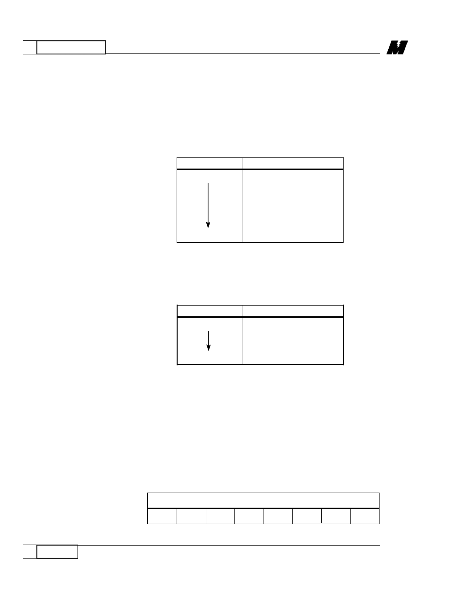
Set memory segment base to 0E000H and I/O memory base to 002E0H by
installing jumper plugs on E1 as shown in Table 1:
Set interrupt source to IRQ3 by installing jumper plugs on E4 as shown in
Table 2:
If a MagneTek TI ROM configuration is used, enable ROM memory by
installing a jumper plug at the /ENROM position of E3.
The node ID is set using the 8-position DIP switch, SW1. Enter the binary node
ID by choosing either a "0" or "1" for each bit. The least significant bit (LSB)
and the most significant bit (MSB) positions are labeled on the board. The LSB
is toward the top of the board. Leaving the switch in the down position sets the
switch at "0". For example, node ID 200, represented in binary form as 11 0 0
1000, is set as shown in Table 3:
S e t u p
Table 2. E4 Settings
POSITION
JUMPER
IRQ2
NO
YES
NO
NO
IRQ7
NO
Table 3. DIP Switch SW1 Settings
MSB
LSB
UP
UP
DN
DN
UP
DN
DN
DN
M i c r o Tr a c
N e t w o r k
Interface Card
Table 1. E1 Settings
POSITION
JUMPER
TOP
YES
YES
NO
NO
NO
YES
NO
BOTTOM
YES
RD 3056-10