Modicon i/o interface card – Yaskawa Modicon 800 Series Remote I/O Network for use on Microtrac LAN User Manual
Page 6
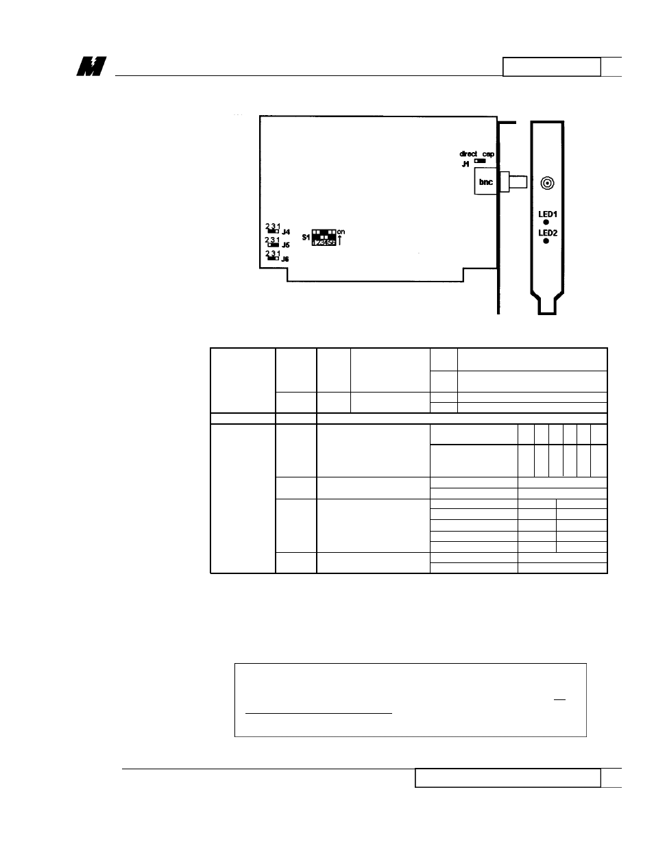
Table 2. Modicon I/O Interface Card Setup
indicates if
off
card is loaded with software
LED1
green
card is
(normal)
LEDs
loaded with
on
card needs to be loaded with
software
software
LED2
red
power indicator
off
no power to gateway
on
power on gateway (normal)
Connector
bnc
connects to Modicon remote i/o network
the host computer
base port address 1 2 3 4 5 6
uses a block of
Switch
S1
8 I/O address to
0x260
o o o o o o
control the operation
(default)
n n f f n n
of the card (download)
f f
J6
enable power up
enabled (default)
2-3
memory
disabled
1-3
Jumpers
base address
J4 J5
the interface card uses
0x9000
2-3 2-3
J4,
a block of 64K bytes of
0xA000
1-3 2-3
J5
memory in the host
0xC000
1-3 1-3
computer
0xD000 (default)
2-3 1-3
J1
method of grounding
through R-C circuit
cap (default)
bnc shield
directly to ground
direct
2
HARDWARE
5
Modicon I/O Interface Card
5/24/96
This card is connected to the Modicon 800 Series I/O network using a coaxial
cable connected to the BNC connectors on the front of the card. It is
connected to the network in the same way as the real drops. Refer to the
Modicon installation guide for information on appropriate types of cable.
CAUTION
The card does not contain a 75-ohm termination resistor, so an
external resistor is necessary at the card end of the cable. (Use
supplied bnc in-line terminator.)
Modicon I/O
Interface Card
RD 3004-20