Yaskawa VS-616G5 Profibus-DP Control Card SI-P User Manual
Page 6
Page 6
VS-616G5 Option Instruction Manual: Profibus-DP Control Card SI-P
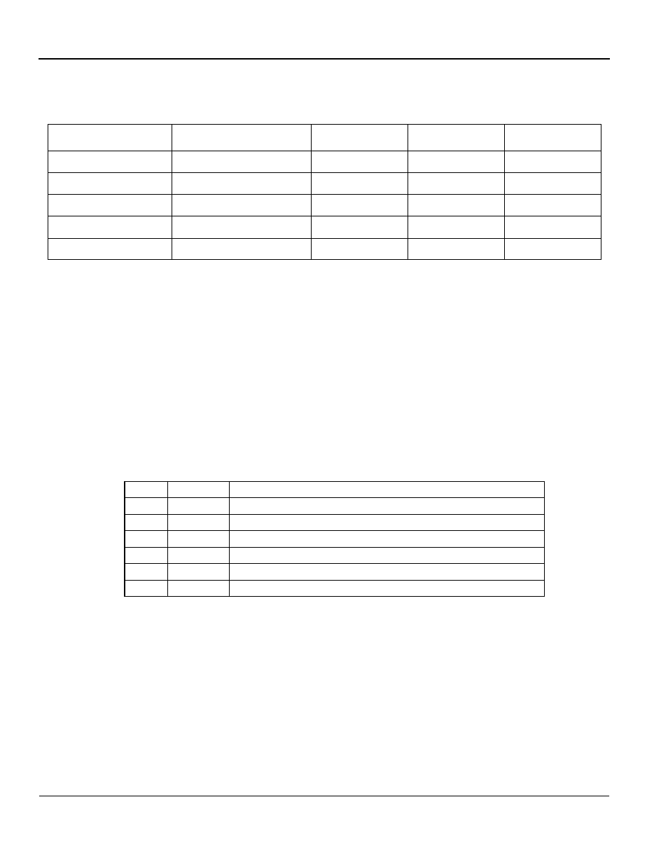
Wiring Terminal Block TC1
The Profibus organization only specifies the pin layout of a 9-pin D-SUB for the terminal
block. The terminal block on the option card follows the pin layout of the connector on the
SI-P option card which has been tested and approved by the Profibus organization.
* Optional pins. Not used in a standard RS 485 Profibus-DP installation.
Table 1: Applicable Wire Sizes for Terminal Block TC1
Wire / Installation Type
Cross-sectional Area [mm
2
]
AWG
I [A]
VAC [V]
Thin twisted wire
1
16
12
125
Solid Wire
1.5
16
12
125
UL
—
22-16
10
300
CSA
—
26-16
10
300
CSA
—
26-16
10
150
Table 2: External Function Terminals of the SI-P Option Card
Pin #
Name
Function
1
+5V BUS
Isolated +5V from RS 485 side *
2
GND BUS
Isolated GND from RS 485 side *
3
A-Line
Positive RxD/TxD according RS 485 specification
4
B-Line
Negative RxD/TxD according RS 485 specification
5
Shield
BUS cable shield. Connected to PE internally on the option card
6
RTS
Request To Send *