Yaskawa VS-616G5 Profibus-DP Control Card SI-P User Manual
Page 8
Page 8
VS-616G5 Option Instruction Manual: Profibus-DP Control Card SI-P
Termination resistor
The option card is equipped with an internal termination resistor that is activated by a
DIP switch located next to terminal block TC1. The bus cable has to be terminated at
both ends of the cable. If the option card is connected as the last unit on the bus, the
termination switch must be in the ON position. Note that if EN50 170 is to be followed,
then Pin 1 +5V BUS and Pin 2 GND BUS must be utilized.
Address configuration
The card is equipped with two decimal (0-9) rotary switches for address set-up. The
switches are located next to the termination switch.
The address is calculated in the following way:
Address = (Switch 1 x 10) + (Switch 2 x 1)
Baud Rate
The baud rate settings are handled automatically by hardware. The ASIC on the option
card listens for valid Profibus-DP (PDP) telegrams from the master PLC on each from
9600 to 12Mbits/s. When a correct PDP telegram has been received from the master
PLC, it will lock onto the current baud rate. The master PLC is continuously sending
PDP telegrams.
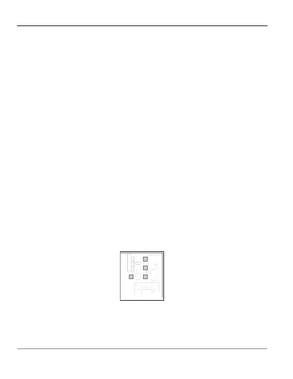
Option Card LED’s
The option card is equipped with four LED’s for indicating option card and Profibus-
DP status. The LED’s are located on the card according to Fig. 5.