Single drive installation, Wiring diagram, 5 installation procedure – Yaskawa V1000 Option 24 V Power Supply User Manual
Page 14
5 Installation Procedure
14
YASKAWA ELECTRIC TOBP C730600 27B V1000 Option PS-V10 Installation Manual
◆
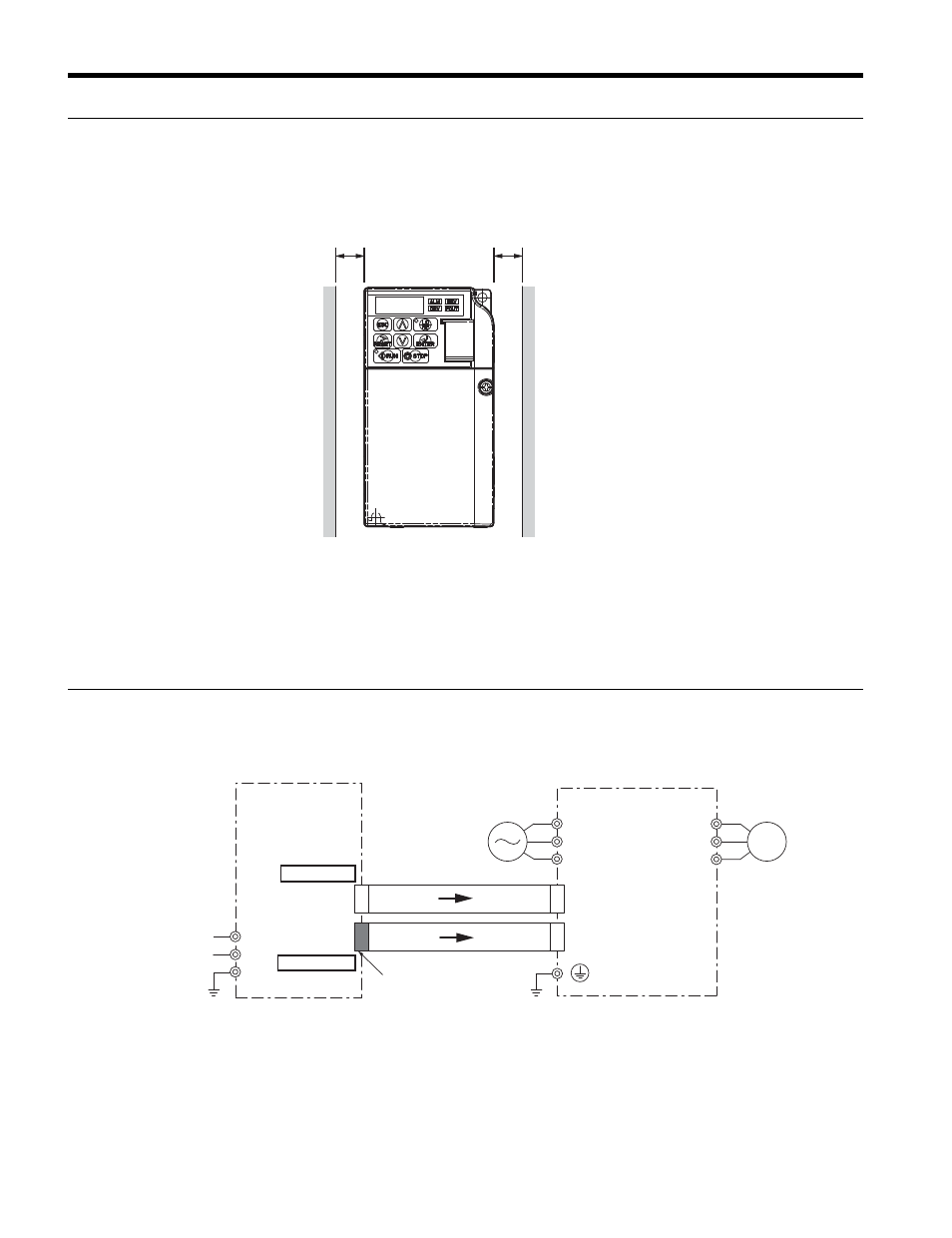
Single Drive Installation
To maintain sufficient space for airflow and wiring with the 24 V Power Supply Option
Figure 4
Figure 4 Correct Installation Spacing
Note: 1. IP20/NEMA Type 1 and IP20/Open-Chassis models require the same amount of space above and below
the drive for installation.
2. Yaskawa recommends unmounting the drive to simplify installation of the 24 V Power Supply Option.
◆
Wiring Diagram
illustrates the 24 V Power Supply Option and drive interconnections.
Figure 5
Figure 5 Connection Diagram for Drive and 24 V Power Supply Option.
A – 30 mm minimum
A
A
R/L1
T/L3
S/L2
U/T1
V/T2
W/T3
Motor
AC input
Drive
+
−
FE
24 V
0 V
24 V Power
Supply Option
24 V Power
Supply Input
CN3-2
CN3-1
CN3 (Controller PCB)
CN3 (Power PCB)
Black
socket
Note 2: This cable with “black” connector ends
is supplied with the PS-V10S Option
Note 1: This cable with “white” connector ends
is supplied with the PS-V10M Option
To Controller
To Pwr Board
Note:2
Note:1