6 verifying operation, Procedure, Power supply and the control circuit – Yaskawa V1000 Option 24 V Power Supply User Manual
Page 29: 6verifying operation
YASKAWA ELECTRIC TOBP C730600 27B V1000 Option PS-V10 Installation Manual
29
6 Verifying Operation
6
Verifying Operation
After properly wiring and installing the 24 V Power Supply Option, use the following
procedure to check for normal operation.
◆
Procedure
1. Make sure the drive main circuit power is on and 24 V external power is supplied to the 24
V connector plug. Switch off the main power supply to the drive. The 24 V external power
supply should provide power to the drives control circuit.
2. A green LED on the 24 V Power Supply Option indicates proper operation.
3. The LED operator (or the LCD operator) on the drive should display “Uv” for about 10
seconds to indicate an undervoltage situation.
Note: If “Uv” does not flash on the display screen, check the wiring. If “Uv” fails to appear on the
display screen after confirming proper wiring, the drive may be damaged.
◆
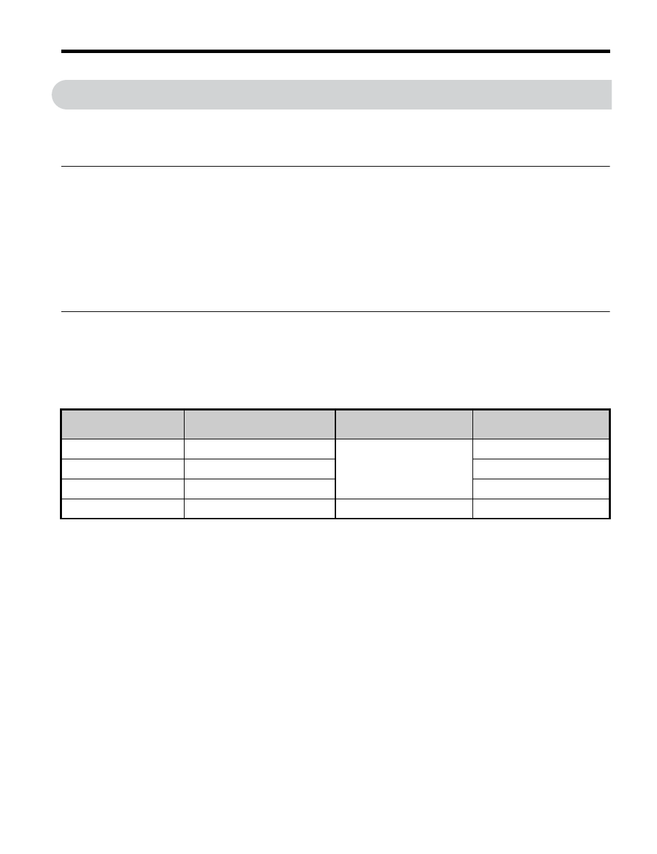
Power Supply and the Control Circuit
outlines the various conditions under which the 24 V Power Supply Option provides
power to the control circuit.
Table 8 Power Supply and Control Circuit
Drive Main Circuit
Input Power Supply
Power from 24 V Power
Supply Option
Control Circuit
Operation in Drive
Drive Operation
ON
ON
Normal operation
Possible
ON
OFF
Possible
OFF
ON
Not possible
OFF
OFF
Stop
Not possible