5 installation procedure – Yaskawa V1000 Option Mechatrolink-II SI-T3/V User Manual
Page 19
5 Installation Procedure
YASKAWA ELECTRIC TOBP C730600 49A V1000 Option MECHATROLINK-II Installation Manual
19
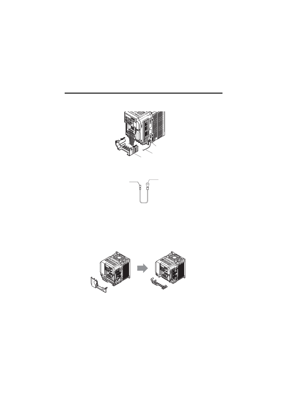
3.
Remove the bottom cover and connect the MECHATROLINK-II Option ground
cable to the ground terminal
.
Figure 6
Figure 6 Connect Ground Cable
Note: The four different ground cables packaged with the MECHATROLINK-II Option connect the
unit to different models. Select the proper ground cable from the MECHATROLINK-II Option
kit depending on drive size.
Figure 7
Figure 7 Ground Cable
Note: Remove the terminal cover
before removing the bottom cover to install the
MECHATROLINK-II Option. Replace the terminal cover after wiring the MECHATROLINK-II
Option.
Figure 8
Figure 8 Models with Terminal Cover
A – Option unit connection: screw size = M3
B – Drive-side connection: screw size = M3.5 to M6
<1> Models with a Terminal Cover:
-Single-Phase 200 V Class: CIMR-V BA0006 to BA0018
-Three-Phase 200 V Class: CIMR-V 2A0008 to 2A0069
-Three-Phase 400 V Class: All models
Ground terminal
Ground cable
Bottom cover
A
B