Mechatrolink-ii communications cables – Yaskawa V1000 Option Mechatrolink-II SI-T3/V User Manual
Page 21
5 Installation Procedure
YASKAWA ELECTRIC TOBP C730600 49A V1000 Option MECHATROLINK-II Installation Manual
21
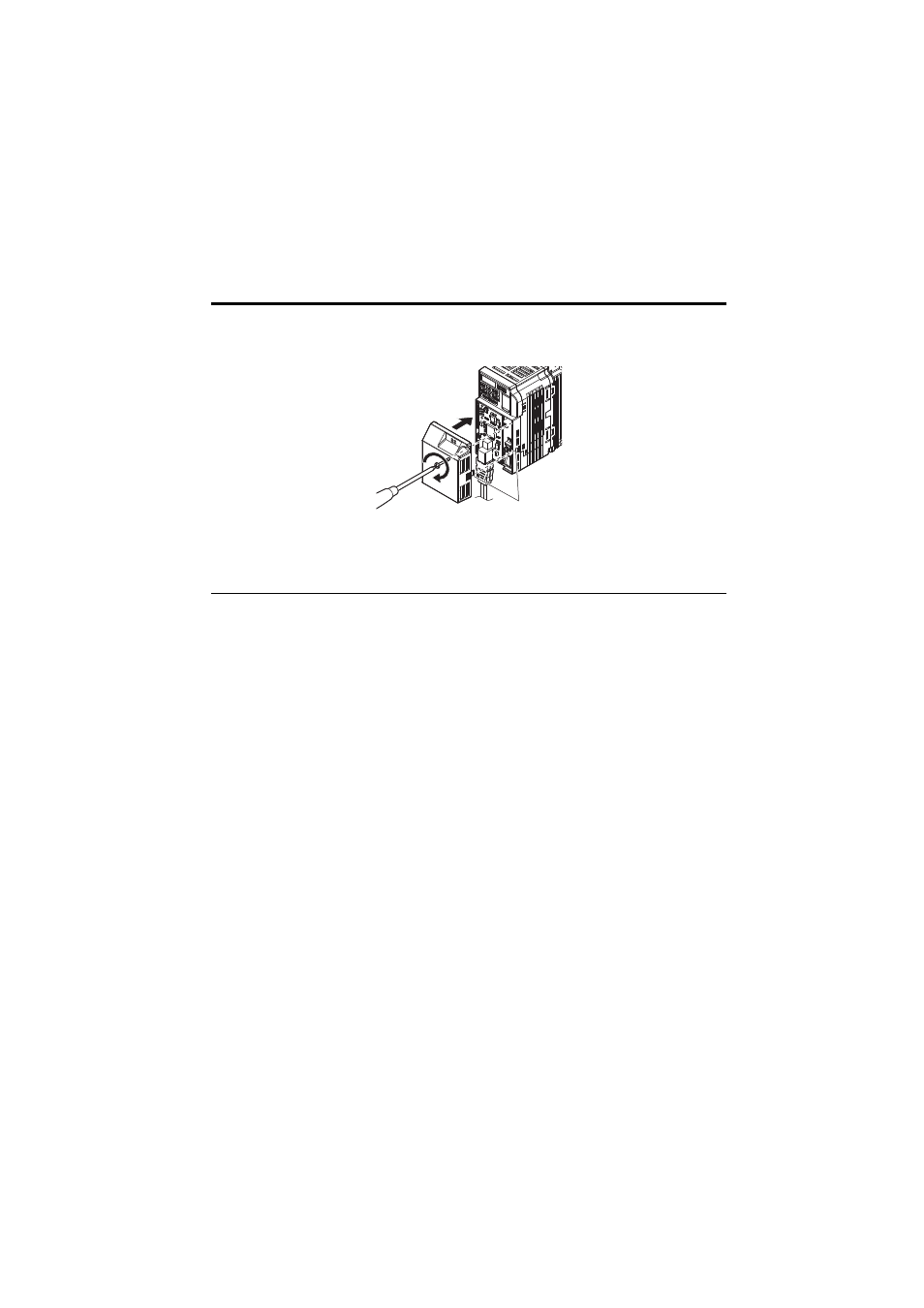
8.
Attach the MECHATROLINK-II Option cover to the front of the MECHATROLINK-II
Option.
Figure 11
Figure 11 Attach Cover
Note: When using the drive in an area that may require displaying warning information in Japanese or
Chinese, a sticker has been provided with the MECHATROLINK-II Option. This sticker can be
placed over the English and French warnings on the front of the MECHATROLINK-II Option.
◆
MECHATROLINK-II Communications Cables
Wire the MECHATROLINK-II communications cables to the communications connector
(CN3). Install MECHATROLINK-II communications cables apart from main-circuit wiring
and other electrical and power lines.
Note: 1. For communications cables, use special shielded twisted-pair cables for MECHATROLINK
communications.
Recommended cable: JEPMC-W6002--E
JEPMC-W6003--E (with a core)
2. Connect the terminator (model No.: JEPMC-W6022-E) on the end of the communication lines.
3. Maximum transmission distance is 50 m. Minimum wiring distance between stations is 0.5 m.
<1> is the length (m).
Tabs should line up