Caution – Yaskawa SmartTrac DeviceNet Card User Manual
Page 17
SMART TRAC DeviceNet Card
Technical Manual 3554-0070 Installing the Smart Trac DeviceNet Card
••
13
Connecting the Smart Trac DeviceNet
Card to a DeviceNet Network
1. Connect a DeviceNet cable to the 5-pin connector at J2. The connector
conforms to the standard DeviceNet pinout (see Table 2). A DeviceNet
Master (the Smart Trac AC1) is typically at one end of the trunk line,
installed with a terminating resistor.
NOTE: Typically, a Master DeviceNet unit installed at one end of the trunk line
and NOT on a drop cable.
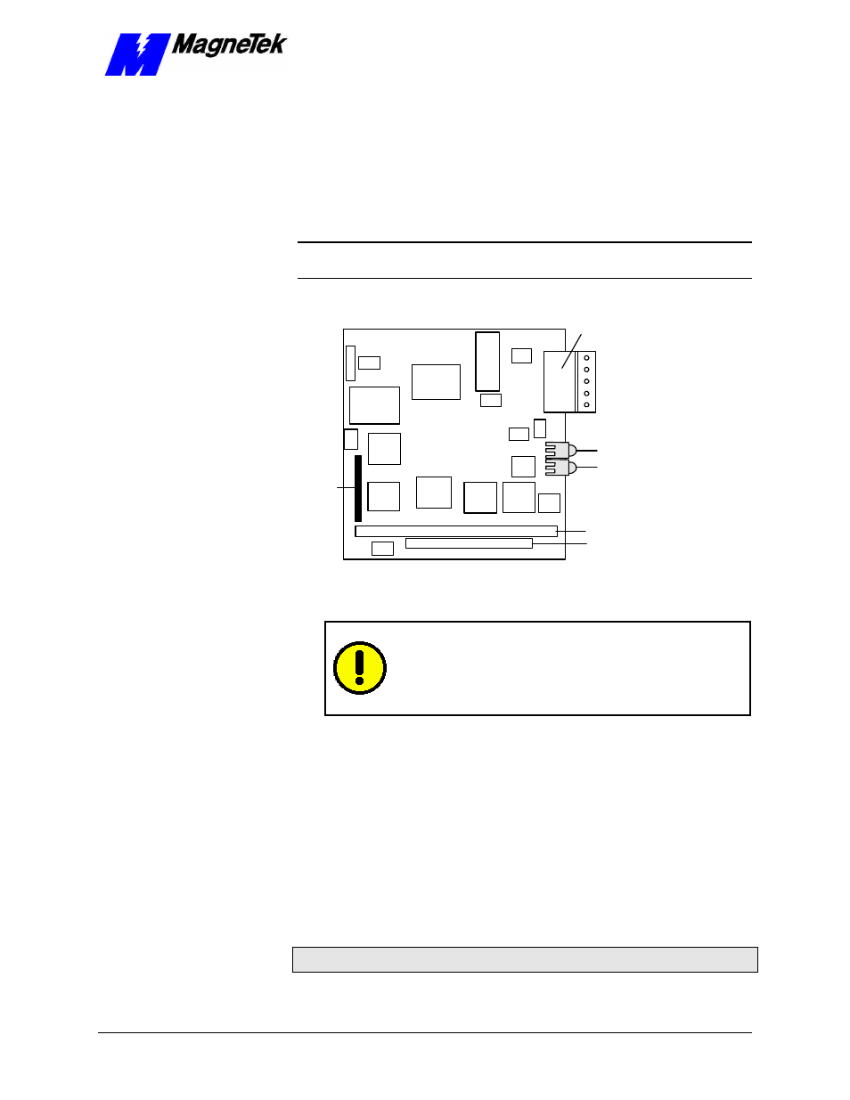
PC/104 Connector
PC/104 Connector
Module Status (MS)
5
4
3
2
1
Network Status (NS)
J2
SW1
P1/P3
P2/P4
Figure 6. Smart Trac DeviceNet Card layout.
CAUTION
CAUTION
Ensure all strands of wire go into connector. Bent strands may
cause shorts to the adjacent terminal. Failure to comply may
result in damage to the DeviceNet card or Smart Trac
electronics.
2. If your Smart Trac AC1 is at the end of DeviceNet network, connect a
120-ohm resistor from pin 2 to pin 4 of the 5-pin connector at J2.
Connector pinouts are described in Table 2.
Table 2. DeviceNet connector pinout
Smart Trac DeviceNet Card 5-pin Connector