Mounting the controller, Installing electrical conduit – Irritrol Total Control-R Series User Manual
Page 22
20
MOUNTING THE CONTROLLER
OUTDOOR MODEL
1. Place the mounting template (provided) on the wall, positioning
the controller display area (indicated on the template) at or
slightly below eye level. Using a small punch or nail, mark the
locations of the top and bottom centerline mounting holes and
the additional lower hole if extra cabinet support is desired.
2. Drill pilot holes at least 1-1/4" (32mm) deep into the wall using a
3/32" (2.5mm) drill for wall stud, or 1/4" (6.5mm) for masonry.
3. For the masonry wall installation only, insert plastic screw anchors
into the pilot holes.
4. Open the cabinet door and swing out the control module by
pressing in on the release latch.
5. With the cabinet door and control module in the open position,
turn the controller over, resting it face down on a clean smooth
work surface.
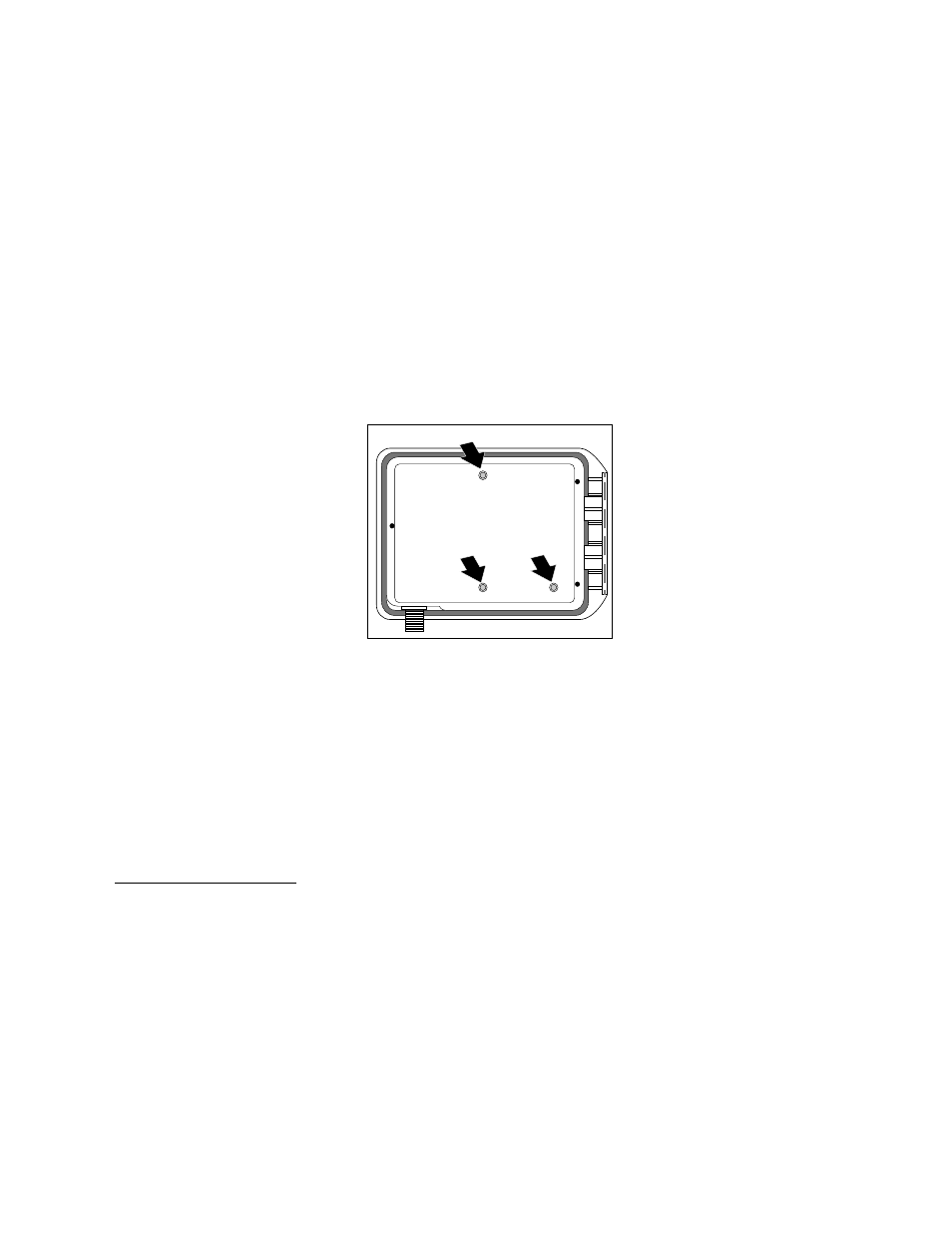
6. Using a 3/16" (5mm) drill,
carefully drill through the
center of the mounting hole
locators on the back
of the controller cabinet.
See Figure 5.
7. Align the cabinet mounting
holes with the wall pilot holes.
Using the #10 x 1" (25.4mm)
phillips head screws, securely
fasten the cabinet to the wall.
INSTALLING ELECTRICAL CONDUIT
Note: Electrical conduit and adapters are not supplied with the
controller but may be required for installation in your area. Check
local electrical codes and install conduit according to requirements.
1. For the outdoor controller power wires, install a 1/2" NPT threaded
conduit access body to the transformer assembly threaded nipple.
From the access body, install conduit to the source point of
connection. (Domestic and international models only.)
2. For field (low voltage) wiring, install a 1-1/2" (38mm) conduit
adapter and conduit.
Installation Procedures
Figure 5
Outdoor Model