Connecting the valve wiring, Figure 6, Installation procedures – Irritrol Total Control-R Series User Manual
Page 23
21
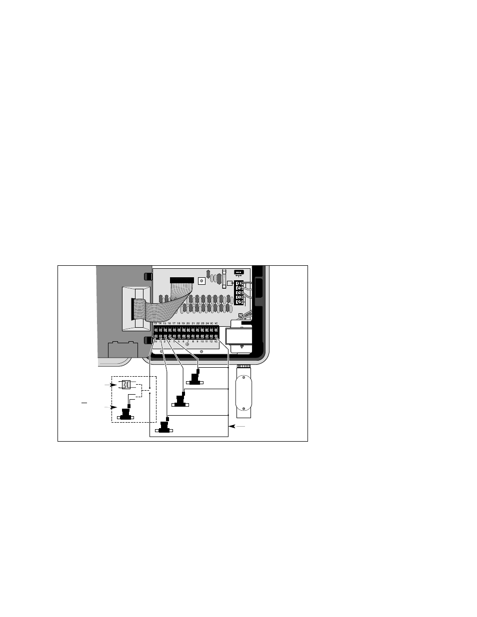
CONNECTING THE VALVE WIRING
1. To provide a field common wire, attach one wire to either solenoid
lead of all sprinkler valves and master valve (optional).
2. Attach a separate control wire to the remaining solenoid lead of
each valve. Label the control wires with the intended station
number for identification at the controller.
Caution: All wiring splices must be waterproofed to prevent short
circuits and corrosion.
Caution: A maximum load of 12 VA (0.5 amps) may be connected
to each station. A maximum load (including master valve) of 30 VA
(1.25 amps) may be programmed to operate simultaneously.
Exceeding these limits can damage the controller.
3. Route the control and common wires into the controller cabinet
through the bottom access opening. Remove approximately
1/2" (13mm) insulation from the ends of each wire.
4. Attach the field common wire to one of the three valve common
terminals labeled “VC.”
5. Referring to Figure 6 connect each valve control wire to the
appropriate station number terminal. If an optional master valve is
installed, connect its control wire to the terminal labeled “MV.”
Tighten all terminal screws securely.
Installation Procedures
ACTIVE
24V
EARTH
GND
AC
G
N
D
BYPASS
SENSOR
SENSOR
VALVE
TEST
Pump Start
Relay
or
Master Valve
Field Common
Figure 6
Valve
Sta. 3
Valve
Station 2
Valve
Station 1