iSys i24 Direct Imaging Printer User Manual
Page 7
i24 USERS GUIDE - 3.31.2005
6
4 CABLE
CONNECTIONS
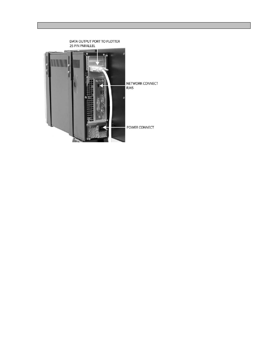
4.1
Installing data cable to the plotter.
I. Push the black button on the left side panel of the plotter.
II. With the black button sticking out, pull on the button to open the side panel exposing the data
bulkhead.
III. Install the 36 pin connector data cable into the bulkhead and secure thumbscrews.
IV. Slide cable into the exit slot on the bottom back corner and close side panel.
V. To lock side panel, press the black button.
4.2 Installing data cable to the RIP.
Install 25 pin connector data cable to the Parallel (lpt out) port on the rear of the RIP box.
4.3
Installing the AC power cord to the RIP box and connecting to network.
Install power cord and network to connectors on rear of the RIP box.
4.4
Installing the AC power cord on Plotter.
WARNING:
Electric shock warning.
I. Push the black button on the right side panel.
II. With the black button sticking out, pull on the button to open the side panel exposing the AC
receptacle.
III. Plug the supplied AC power cords into the receptacle.
IV. Slide cord into the slot on the bottom back corner and close side panel.
V. To lock side panel, press the black button.