Important, Attention – KACO Powador-proLOG User Manual
Page 10
Operating Instructions Powador-proLOG_EN
Page 11
S e c t i o n 5 ·
I n s t a l l a t i o n
Strain relief
When connecting the 230 V AC power cable (included in the
scope of delivery), we recommend that you use a cable grip
to attach it to the assembly rail inside the housing. The fi gure
below shows an example cable grip design.
5.4.2 GSM antenna (XL GSM/GPRS)
5.4.3 Powador-go (M / XL)
The current sensors are connected and supplied with
power using patch cables. The ports are labelled
“Powador go” (RJ45 sockets).
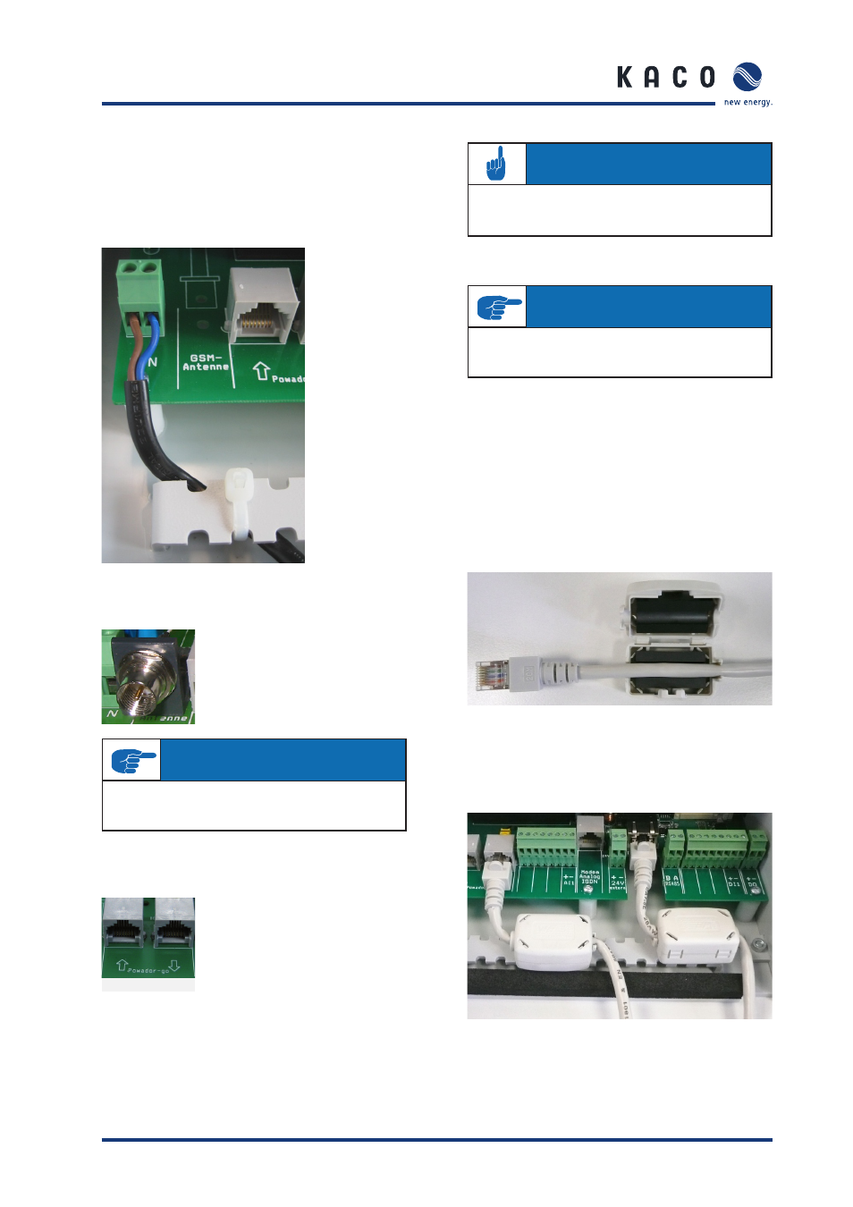
Installing the ferrite clips
To prevent possible communication faults caused by electro-
magnetic radiation, ferrite clips are included with the Powa-
dor-proLOG M. The installation process is shown in the two
images below.
a)
Insert the patch cable (RS485) into the ferrite clip
and close it.
b)
Connect the patch cable to the Powador-go
port on the Powador-proLOG and attach the
ferrite clip to the assembly rail (e.g. cable ties).
Connect the GSM antenna supplied
here. The connection is located to the
far left, between the grid connection
and the Powador-go RJ45 sockets.
You can connect up to 100 cur-
rent sensors (Powador-go) to the
“Powador-go” RJ45 sockets. For exam-
ple, you can use the current sensors
to include inverters without RS485 in
monitoring.
IMPORTANT
For more information on the Powador-proLOG
with GSM modem, see section 6.5 on page 22.
ATTENTION
The internal power supply can be used to supply
power to a maximum of six current sensors.
IMPORTANT
When you have more than 32 bus devices,
you need to use a repeater.