Chapter 3, Motherboard information, Motherboard layout – Lanner FW-8895 User Manual
Page 16: Network application platforms
Advertising
12
Motherboard Information
Chapter 3
Network Application Platforms
J22
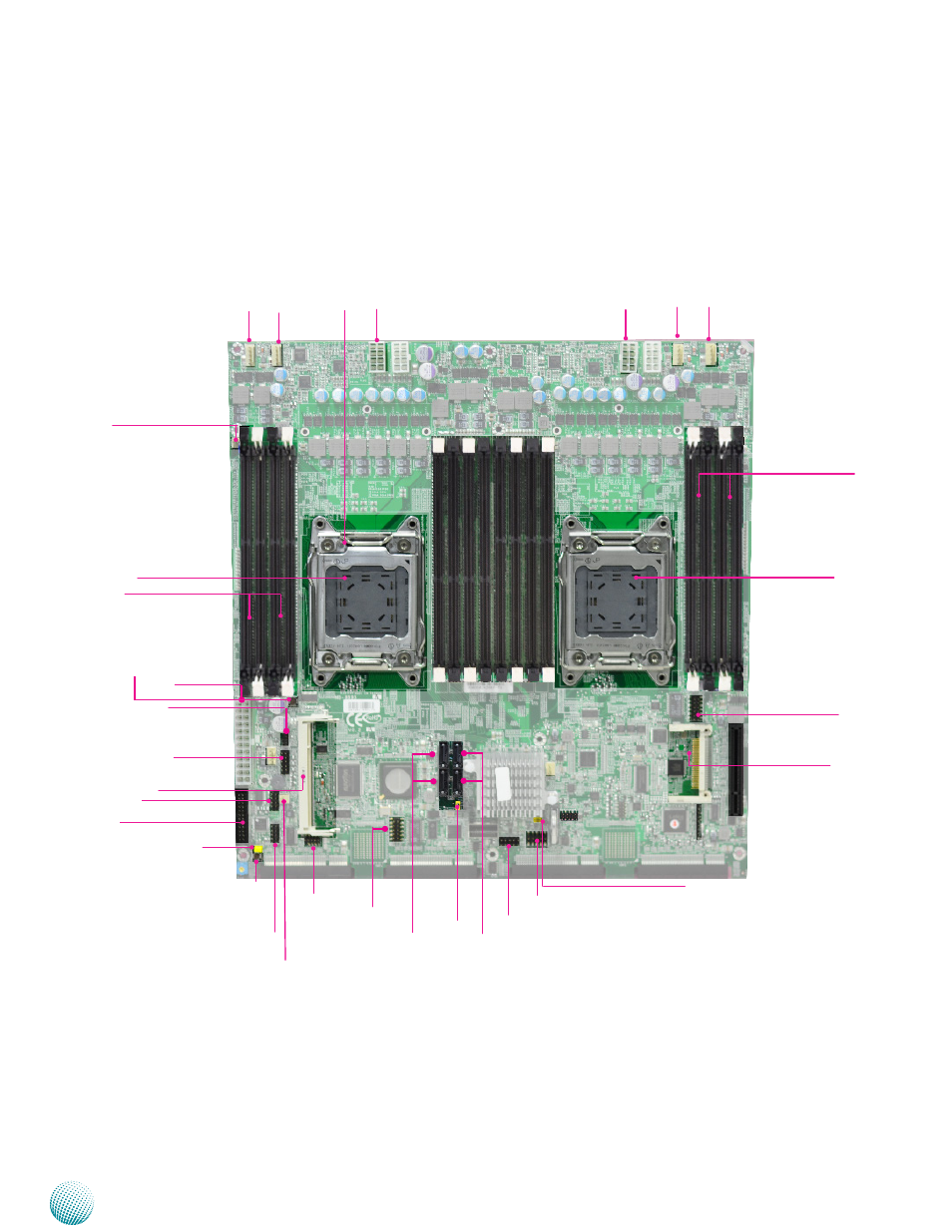
Motherboard Layout
The motherboard layout shows the connectors and
jumpers on the board. Refer to the following picture
as a reference of the pin assignments and the internal
connectors.
CF Card Connector, CF1
COMB1
DIMM Socket
Reset Switch (SW2)
Management Port, MGT1
Fan 1
DIMM Socket
CPU Socket
No.1
VGA1
Management Port, MGT2
AT Mode Power Button Con-
nector (CONN1)
COMA1
OPMA Connector
Front Panel LCD Connector (J23)
SATA2
SATA 1
Fan 4
Fan 2
Fan 3
ATX3
ATX1
CPU Socket NO. 2
Front LCM in USB (LCM_1)
USB2
USB1
ATX5
CPU Socket NO. 1
CMOS (J24)
Power Switch (SW1)
SATA4
SATA3
OPEN2
J27
OPEN1
Advertising
This manual is related to the following products: