Chapter 3, Motherboard information – Lanner FW-8895 User Manual
Page 20
16
Motherboard Information
Chapter 3
Network Application Platforms
OPEN2: A switch to switch the output signal
between MGT2 and OPMA1 since they share
the same access port (the management port
on the front panel). To let the MGT2 signal pass
through instead of the OPMA signal, take out this
jumper. In this way, you could have both VGA and
Management connections.
Note: To have both VGA and Management (non-
IPMI compliant) connections, take out the jumper
block.
J27: A reset switch to switch between hardware and
software reset function for the front panel reset button.
A hardware reset function will reset the whole system
while a software reset function will reset the designated
software to its default value.
OPEN1: Case open detection jumper. Use this to
detect case open event.
J24: Clear CMOS Jumper. Use this jumper to reset the
BIOS setting to its factory default.
3 2 1
CPU Socket NO.1 and CPU Socket NO. 2: When
using only one CPU, install the CPU on the socket NO.1 or
the system will not function.
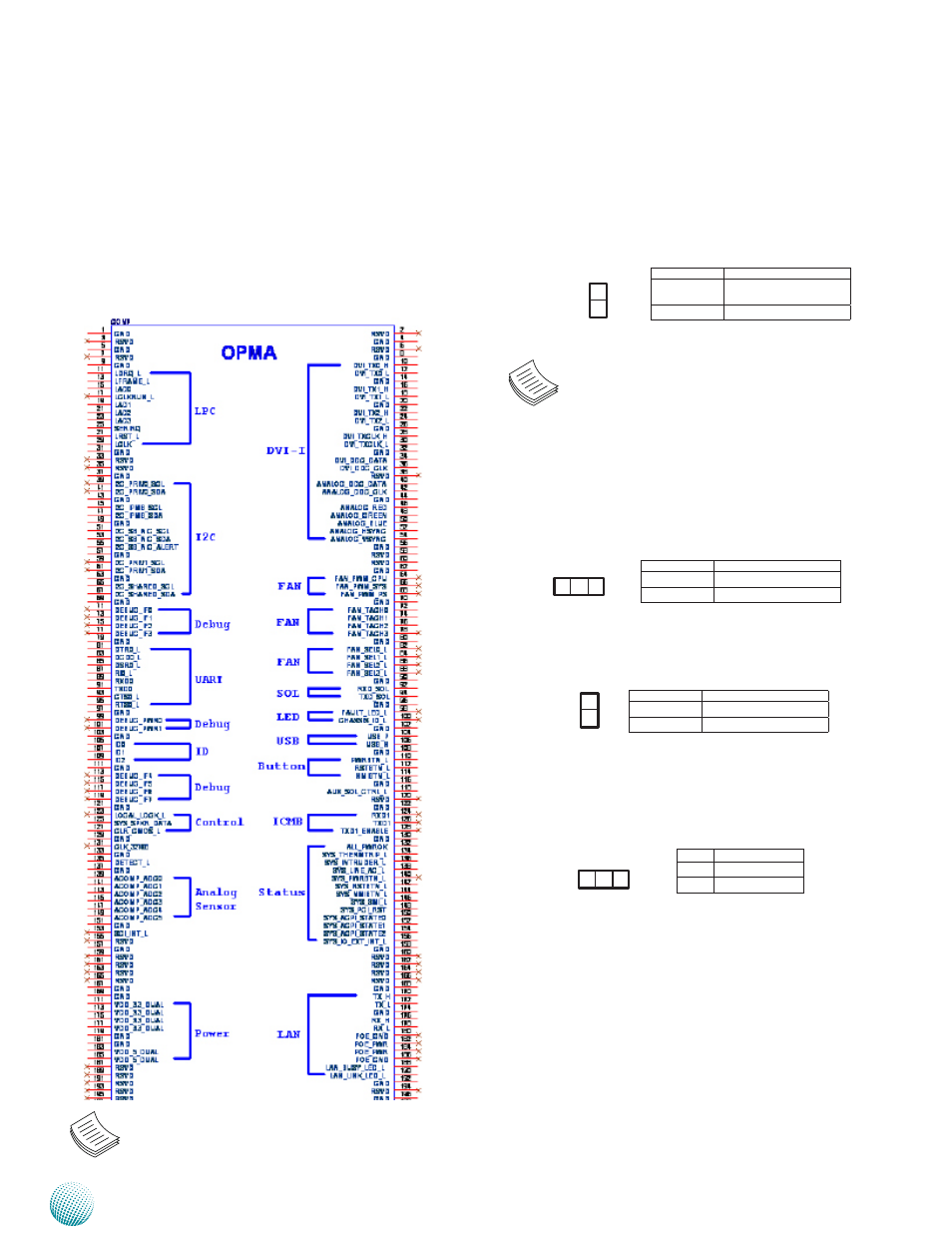
OPMA1: OPMA Connector. The OPMA connector
is for connecting the OPMA card. When the OPMA card
is connected, the management port will comply with
the Intelligent Platform Management Interface (IPMI)
standard.
Note: A 2x6 pin (2.0”) header (J1) on the OPMA
card is provided as an VGA interface connector.
Pin No.
Description
Short1-2
IPMI Pass-through
(default)
Open 1-2
MGT2 Pass-through
1
2
Pin No.
Description
1-2
Hardware Reset
2-3
Software Reset
Pin No.
Description
1
GROUND
2
CSOPEN_N
1
2
Pin No.
Description
1-2 Normal (default)
2-3
Clear CMOS
1 2 3